Structure for reducing noise in magnetic resonance imaging apparatus

a technology of magnetic resonance imaging and noise reduction, which is applied in the direction of magnetic measurements, instruments, measurement devices, etc., can solve the problems of distortion of the support member of the gradient magnetic field coil, imperfect support effect of the member, and tendency to increase vibration, so as to reduce the vibration of the gradient magnetic

Active Publication Date: 2008-05-20
FUJIFILM HEALTHCARE CORP
View PDF24 Cites 14 Cited by
  • Summary
  • Abstract
  • Description
  • Claims
  • Application Information

AI Technical Summary

Benefits of technology

[0014]The configuration can be so that the above-mentioned shim tray includes one or more through-holes, and the first support member can be put through that hole. By this configuration, there is no need to provide space for vibration damping separately from the shim tray, and space can be saved.
[0022]The above-mentioned first support member can be placed as not to be contiguous to the shim tray. This will prevent the vibration of the gradient magnetic field generating unit to be transmitted to the shim tray.
[0033]Various examples and exemplary embodiments are described below which can achieve both reduction of the vibration of the gradient magnetic field coil and correction of the nonuniformity of the static magnetic field without expanding the spacing between the gradient magnetic field coil and the static magnetic field generating magnet.

Problems solved by technology

However, in this configuration the static magnetic field generating magnets pull the static magnetic field adjustment unit and causes distortion as a result, and it also causes distortion on the support member of the gradient magnetic field coil.
This distortion creates an air gap between the gradient magnetic field coil and the support member, and the supporting effect of the member becomes imperfect because of it.
The vibration is usually generated in the gradient magnetic field coil by Lorenzo force due to pulsed electric current, but the vibration tends to get bigger when the supporting effect of the support member is deficient.
This leads to the problem of vibration being transmitted to the static magnetic field.
As a result, it leads to the problem of narrowing the imaging region for placing an object to be examined.

Method used


Image

  • Structure for reducing noise in magnetic resonance imaging apparatus
  • Structure for reducing noise in magnetic resonance imaging apparatus
  • Structure for reducing noise in magnetic resonance imaging apparatus

Examples


second embodiment

The Second Embodiment

[0067]An MRI apparatus of the second embodiment is different from the first embodiment in the configuration of support member 25. The descriptions of the other configurations will be omitted since they are the same as the ones in the first embodiment.

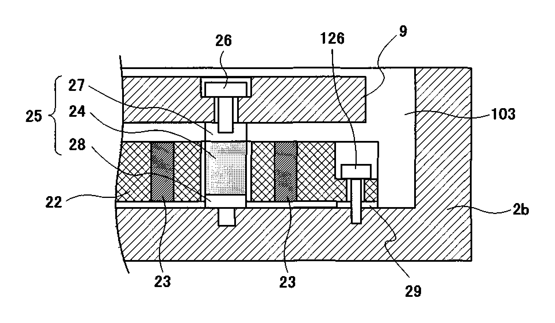
[0068]Support member 25 in the second embodiment, as illustrated in FIG. 5, is using bolt 28 with a structure wherein male-screw 28b is fixed at the bottom part of container 28a being formed by a material with stiffness such as a metal, and vibration-damping member 24 being made of a material such as rubber, is filled inside of container 28a. Pedestal 27 with a screw hole is implanted in vibration-damping member 24. Thus pedestal 27 and container 28a are not touching each other, and are placed with vibration-damping member 24 in between. Gradient magnetic coil 9 is fixed to pedestal 27 by bolt 26.

[0069]Support member 25 in FIG. 5 contains vibration-damping member 24 in container 28b, and has a configuration of impla...

third embodiment

The Third Embodiment

[0071]An MRI apparatus in the third embodiment is different from the one in the first embodiment in the configuration of support member 25. The description on the other configuration will be omitted since they are the same as of the first embodiment.

[0072]Support member 25 in the third embodiment, as illustrated in FIG. 7, is using bolt 28 with a structure wherein male-screw 28b is fixed at the bottom part of container 28a being formed by a material with stiffness such as a metal, and vibration-damping member 24 is filled inside of container 28a. Pedestal 27 with a screw hole is implanted in vibration-damping member 24. Container 28a takes a form that the aperture is narrowed, and is configured in a way that this narrowed aperture is blocked off by pedestal 27, and further sealed with sealing material 150.

[0073]Therefore in this embodiment, other than solid elastic member such as rubber, viscous fluid such as oil, butane series polymer and silicon series polymer,...

fourth embodiment

The Fourth Embodiment

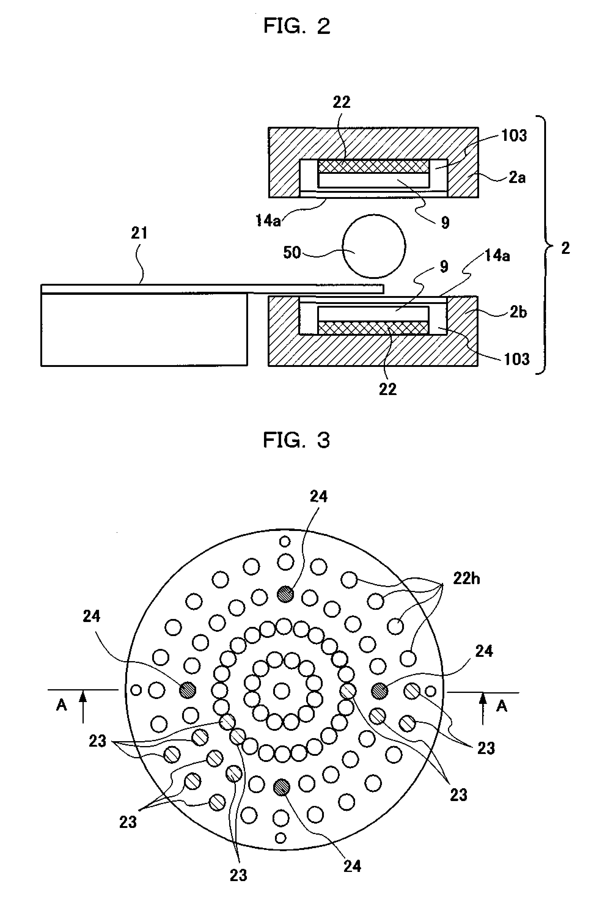
[0076]An MRI apparatus of the fourth embodiment will be described referring to FIG. 8. The MRI apparatus in FIG. 8 further arranged a means for directly reducing the amplitude of vibration mode such as main vibration mode with big amplitude or vibration mode contributing to resonance or noise, being caused in gradient magnetic field coil 9. Concretely, columnar amplitude-suppressing member 124 being formed by an elastic material is set up in through-hole 22h positioned where the amplitude of the vibration mode is high (a loop of the vibration or in the vicinity of it), and reduces the vibration by making the head portion of amplitude-suppressing member 124 touch to gradient magnetic field coil 9 so that the vibration of gradient magnetic coil 9 is directly suppressed. Support member 25 and magnetic piece 23 are to be placed the same way as the first embodiment. The other configuration as well is the same as of the first embodiment.

[0077]Columnar amplitude-suppre...


PUM


Abstract

A magnetic resonance imaging apparatus is provided in which vibration of a gradient magnetic field coil is reduced, the vibration is not transmitted to a static magnetic field correcting unit, and space can be saved.

Description

TECHNICAL FIELD[0001]The present invention relates to a magnetic resonance imaging apparatus (hereinafter referred to as an MRI apparatus), and particularly to its configuration for correcting uniformity of the static magnetic field as well as for reducing vibration and noise from the gradient magnetic field coils.BACKGROUND OF THE INVENTION[0002]The standard MRI apparatuses are those that use cylindrical magnets for generating a static magnetic field which makes the inside of the cylinder the imaging region, and also those that use a pair of magnets facing each other for generating a static magnetic field which makes the space between the magnets the imaging region. The magnets generally used for generating the static magnetic field are permanent magnets, normal-conducting magnets, or super-conducting magnets.[0003]As for the MRI apparatus that uses the facing arrangement type of static magnetic field generating magnets, for example as illustrated in Patent Document 1, the known co...

Claims


Application Information

Patent Timeline
Patent Type & Authority Patents(United States)
IPC IPC(8): G01V3/00G01R33/385G01R33/3873
CPCG01R33/3806G01R33/3854G01R33/3873
Inventor KUROME, AKIRAWADAYAMA, YOSHIHIDE
Owner FUJIFILM HEALTHCARE CORP
Why Eureka
Try Eureka