Shielded, asymmetric magnets for use in magnetic resonance imaging

a magnetic resonance imaging and shielding technology, applied in the field of shielded, asymmetric superconducting and non-superconducting magnets, can solve the problems of high cost, many people suffer from claustrophobia, and physicians cannot easily assist or personally monitor subjects during mri procedures, and achieves the effects of convenient use, reduced cost, and improved imaging performan

Active Publication Date: 2008-05-20
MAGNETICA
View PDF14 Cites 11 Cited by
  • Summary
  • Abstract
  • Description
  • Claims
  • Application Information

AI Technical Summary

Benefits of technology

[0051]The shielded, asymmetric magnets of the invention have the advantage of allowing the part of the body to be imaged to be located very close to the end of the magnet during scanning. This means that the subject can be more comfortable during the procedure and that a greater range of imaging applications are possible. The magnets are particularly advantageous in imaging of a subject's extremities since for these applications, they can have small dimensions which make them relatively inexpensive to manufacture and easy to site in a health care facility.

Problems solved by technology

Not surprisingly, many people suffer from claustrophobia when placed in such a space.
Also, the one-meter distance between the portion of the subject's body which is being imaged and the end of the magnet system means that physicians cannot easily assist or personally monitor a subject during an MRI procedure.
Larger magnets require more shielding and larger shielded rooms for such safe usage, thus leading to higher costs.
While extremity MRI systems have a number of advantages to the subject and the operator, they represent a challenge in terms of the space available for the various coils making up the magnet and in terms of cooling those coils, whether they be superconducting or resistive coils.
The close spacing between coils can also lead to high peak fields in some circumstances, as well as to substantial inter-coil and intra-coil stresses.

Method used


Image

  • Shielded, asymmetric magnets for use in magnetic resonance imaging
  • Shielded, asymmetric magnets for use in magnetic resonance imaging
  • Shielded, asymmetric magnets for use in magnetic resonance imaging

Examples


example 1

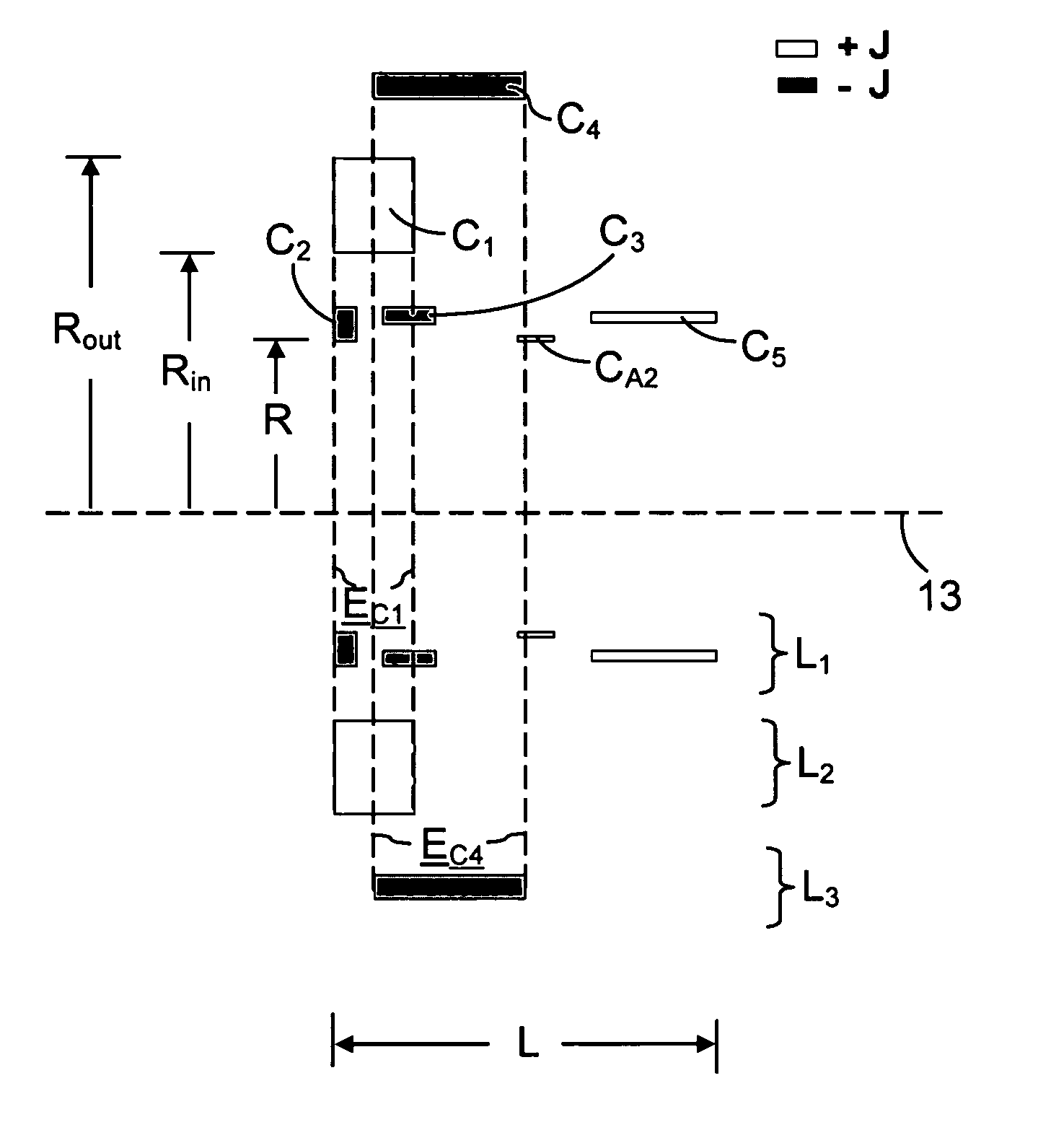
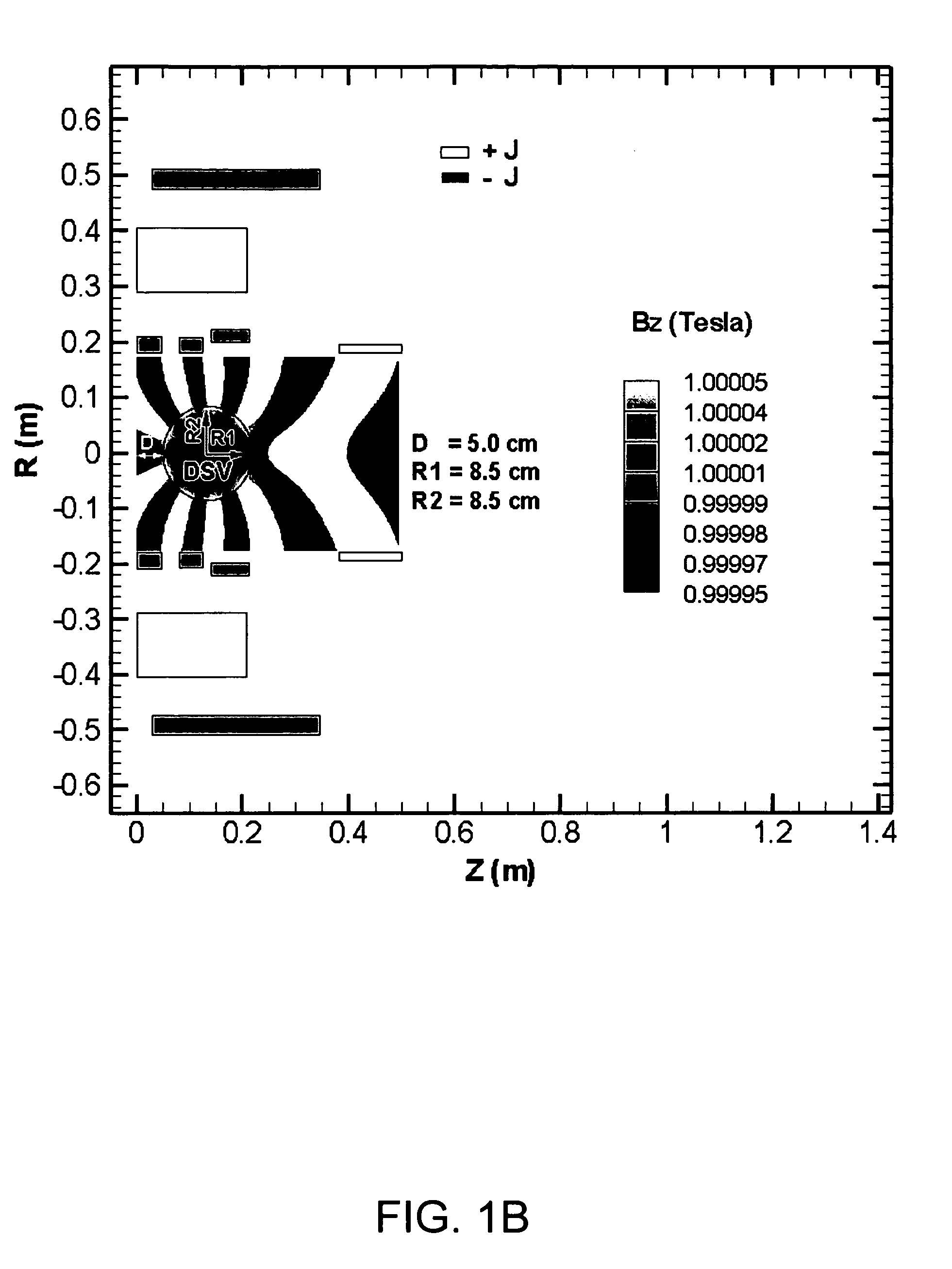
[0110]This example illustrates an asymmetric, superconducting magnet of the present invention. In broad overview, the magnet employs six coils and has a cold bore length (L) and a cold bore inner radius (R) of approximately 0.5 and 0.18 meters, respectively. The magnet employs a positive coil (C5) at the magnet's distal end, and three negative coils located near the magnet's proximal end, all of which are at least partially within the internal envelope (EC1) defined by the magnet's strongest coil (the C1 coil). The magnet employs active shielding provided by coil C4. Two of the magnet's coils (C1 and C4) have lower current densities than the remaining coils.

[0111]FIG. 1A shows the six coils used in the magnet, FIG. 1B shows the calculated axial magnetic field generated by the magnet, including the magnet's dsv, FIG. 1C shows the calculated magnitudes of the total magnetic field generated by the magnet within the magnet's various coils, FIG. 1D shows the calculated hoop stresses in t...

example 2

[0117]This example illustrates a superconducting magnet in which the current density is increased compared to Example 1. Specifically, in Example 1, the current density was 80 amps / mm2 in some coils, while in this example, the current density is 120 amps / mm2 in all coils.

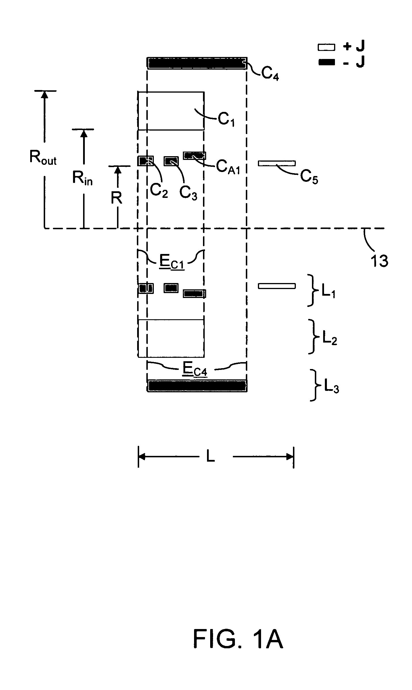
[0118]As shown in FIG. 2A, the strongest coil is now smaller than in Example 1, and instead of three negative coils located near the proximal end of the magnet, the magnet of this example only uses two such coils. However, the magnet now includes an additional positive coil (CA2) so that the total number of coils is again six.

[0119]As in Example 1, the magnet of this example has a cold bore length (L) and a cold bore inner radius (R) of approximately 0.5 and 0.18 meters, respectively. Again like Example 1, the magnet employs active shielding provided by coil C4.

[0120]As shown in FIGS. 2B-2E, the performance of the magnet is substantially the same as that of Example 1, except that the calculated hoop stresses are som...

example 3

[0121]This example illustrates a magnet in which a combination of active and passive shielding is used. Specifically, this example uses an active shielding coil C4 in combination with a ferromagnetic structure FS to produce a low level of stray fields (see FIG. 3E).

[0122]As shown in FIG. 3A, the strongest coil (C1) is again smaller than that used in Example 1. As in Example 2, the magnet has two negative coils (C2 and C3) located near the proximal end of the magnet and an additional positive coil (CA2) which brings the total number of coils used in the magnet to six.

[0123]Table 2 shows the coil geometry and the magnitudes of the current densities in each coil for a constant transport current of 180 amperes. As shown in this table, the current density for each of the coils is 120 amps / mm2. Compared to Example 2, which also used a current density of 120 amps / mm2 for each of its coils, this example exhibits lower calculated hoop stresses because of the use of the ferromagnetic structur...


PUM


Abstract

Magnetic resonance systems are provided which employ a shielded, asymmetric magnet to produce an offset dsv. The magnets include at least a first coil C1, which carries current in a first direction, and two coils C2 and C3, which are located at least in part within the internal envelope EC1 defined by the first coil and which carry current in an opposite direction to the first coil. The magnets are shielded by a shielding coil C4, which carries current in a direction opposite to that of the first coil, and / or a ferromagnetic structure (FS). The magnets can include additional coils, such as a fifth coil C5 at the magnet's distal end. The magnets can be used in, for example, orthopedic imaging.

Description

CROSS REFERENCE TO RELATED APPLICATION[0001]This application claims the benefit under 35 USC §119(e) of U.S. Provisional Application No. 60 / 666,137 filed Mar. 29, 2005, the contents of which in its entirety is hereby incorporated by reference.I. FIELD OF THE INVENTION[0002]The present invention relates to shielded, asymmetric superconducting and non-superconducting magnets for producing substantially homogeneous magnetic fields (B0 fields) for use in magnetic resonance imaging (MR imaging). The shielding can be active, passive, or a combination thereof. The magnets are particularly well-suited for use in producing images of an extremity of a subject, e.g., a subject's limb or head.II. DEFINITIONS[0003]As used herein, the following terms and phrases shall have the following meanings:[0004](1) “Proximal” and “distal” refer to the orientation of the magnet relative to the subject during imaging.[0005](2) The phrase “ends of the magnet” means the farthest outward axial locations of the ...

Claims


Application Information

Patent Timeline
Patent Type & Authority Patents(United States)
IPC IPC(8): G01V3/00
CPCG01R33/381G01R33/3815G01R33/421A61B5/055G01R33/3875
Inventor CROZIER, STUARTLIU, FENG
Owner MAGNETICA
Why Eureka
Try Eureka