[0057]Amongst other factors, the
advantage of the invention by comparison with the prior art is that the extrudate can be introduced in the same operational procedure as the manufacture of the building element; the profiles are very firmly bonded to the core material; when synthetic material is used, the profiles can be milled much more precisely and can therefore be milled to achieve better locking; the extrudate represents a cost-favourable material; the tongues or grooves can be provided with resilient properties independently from the material properties of the core material; and the connecting surfaces do not need to be sealed, because the
absorption of water and
moisture is reduced and / or prevented by the extrudate and / or the synthetic material.
[0058]Potential savings can be achieved with reference to material and transport if the milled material, that is, the material which has been removed from the panel during the milling of the grooves, is mixed with other components and subsequently injected back into the grooves in order to mill the tongue and / or the groove into this material to form a sharp edge. Accordingly, this wooden material need not be procured or transported. Storage and disposal of milling waste are not required.
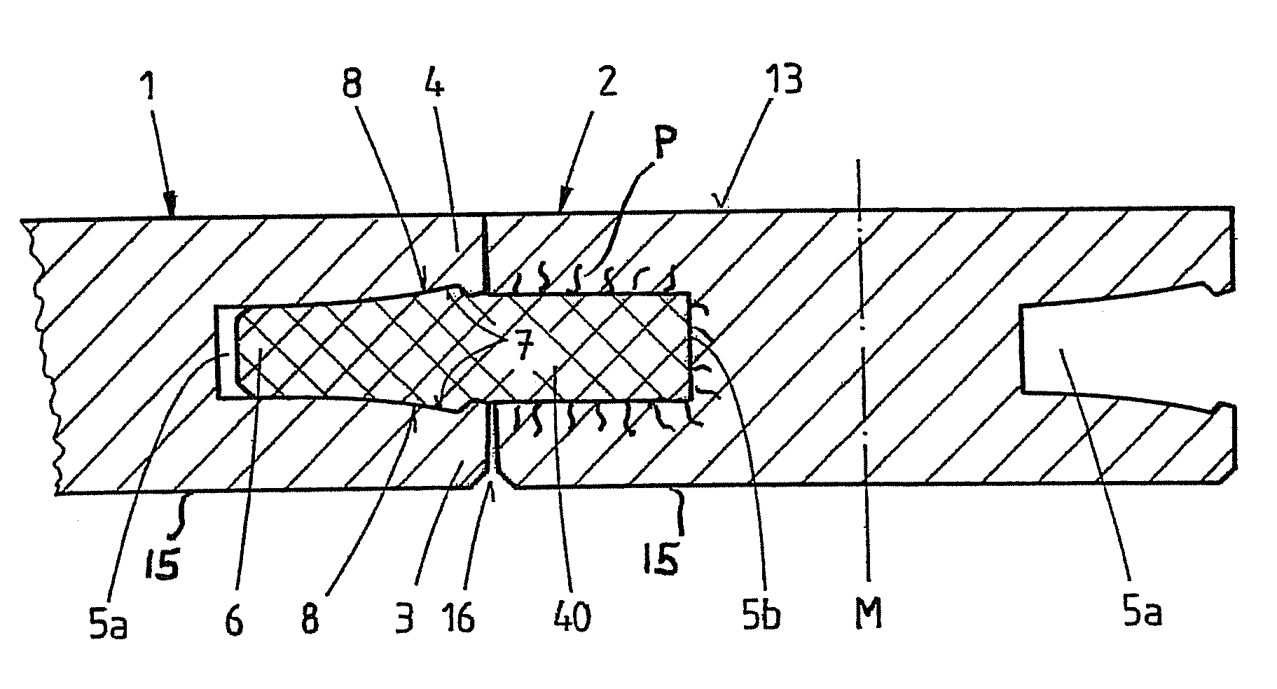
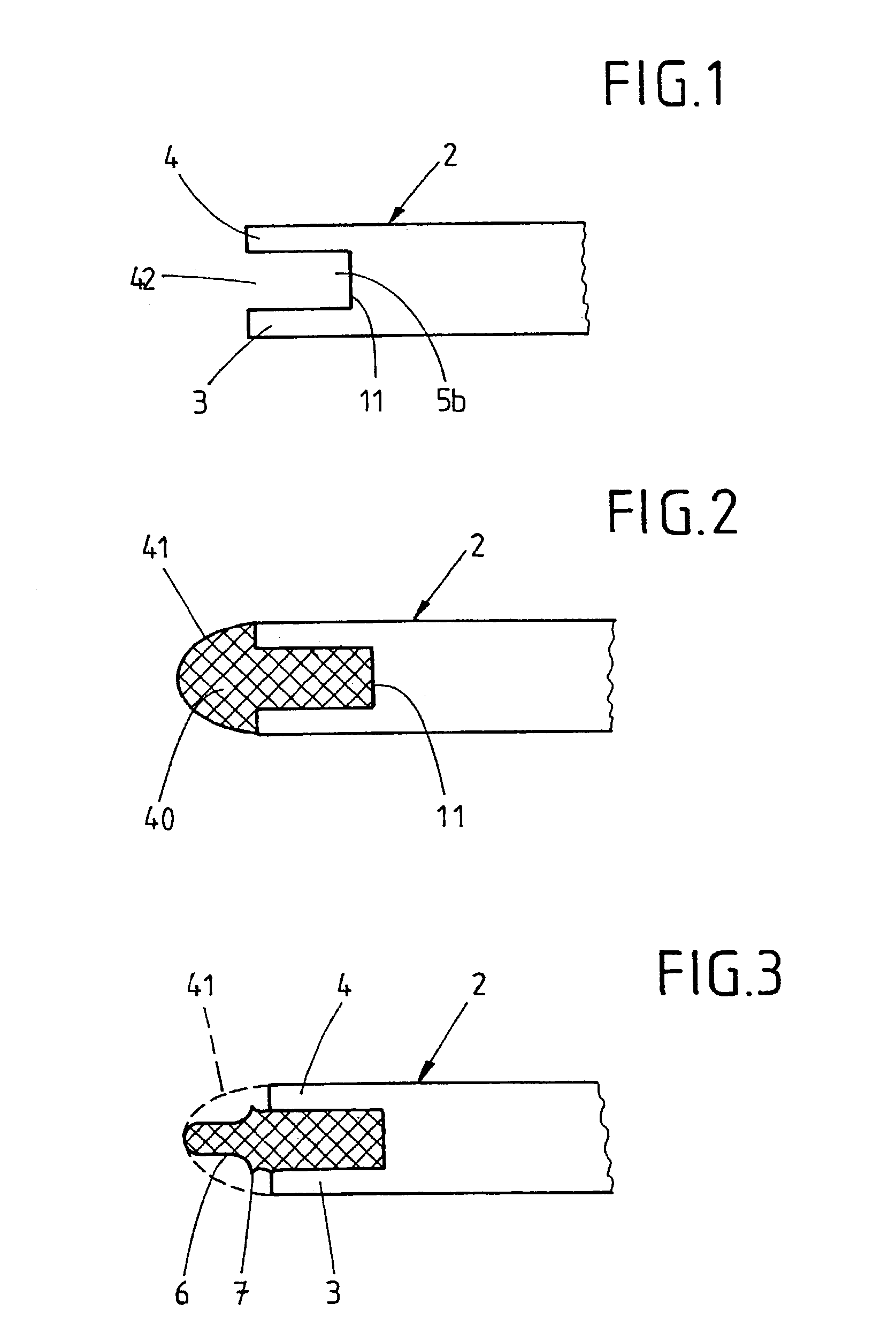
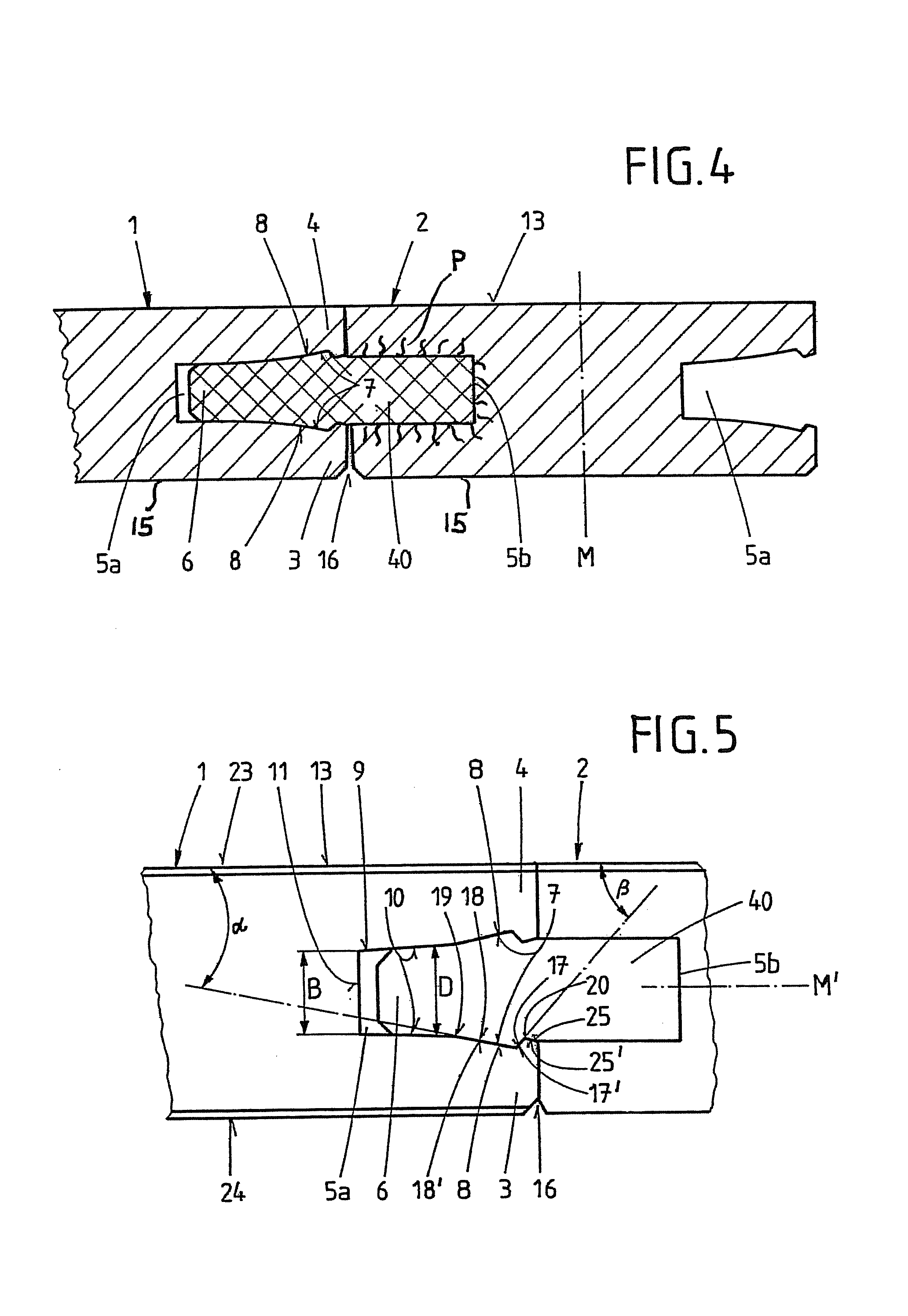
[0059]Furthermore, according to the invention, the extrudate may extend up to the surface of one or both building elements. In this context, it provides an intermediate component, mechanically and visually, along the edges of the building elements. It therefore fulfils a double function, acting as a connecting means and at the same time fulfilling aesthetic, protective and stabilising functions; in the sense of the invention, it is not compulsory for the extrudate to serve as a connecting means.
[0060]If the extrudate forms the end face of the building elements, this edge can be processed more accurately, thereby achieving a more precise fit. This prevents the accidental separation of the connection and the penetration of
contamination into the connection. Furthermore, the connection itself is less visible. The edges of the wooden materials very frequently become splintered i.e. provided with raised fractures in the region of the surface in danger of
impact. Splintering also occurs when
processing the edges. Especially after the panels have been laid, such splinters are very readily visible along the edges if viewed against back lighting. When the extrudate according to the invention extends up to the surface, it can prevent or conceal these edges.
[0061]If the extrudate is water-resistant, it will protect the building element, which is generally
moisture-absorbing, thereby preventing the
absorption of water.
Moisture is known to cause swelling, leading to an unattractive appearance of the building element. Impregnating the edges of the building element, which would normally be carried out for this reason, is therefore no longer required.
[0062]The extrudate acting as an intermediate component can be produced in various materials, structures and colours. Especially when they are coloured, intermediate components of this kind, provide a decorative feature creating visual effects
ranging from the sophisticated to the rustic.

