Deoiler for a lubrication system

a lubrication system and deoiler technology, applied in the direction of machines/engines, liquid fuel engines, separation processes, etc., can solve the problems of unfavorable high idle power setting, unfavorable high idle setting, and compromising lubricating and heat transfer properties, so as to resist excessive buffer air infiltration and reduce air pressure

Active Publication Date: 2008-05-27
RTX CORP
View PDF4 Cites 63 Cited by
  • Summary
  • Abstract
  • Description
  • Claims
  • Application Information

AI Technical Summary

Benefits of technology

[0008]It is, therefore, an object of the invention to provide a deoiler that reduces the bearing compartment pressure, particularly at lower engine power settings.
[0009]It is a further object to provide a deoiler that can also pressurize the bearing compartment at higher power settings.
[0010]It is another object of the invention to provide a method of deoiling that reduces pressure at a source of oil-contaminated air at one operating condition and that can pressurize the source of contaminated air at a second operating condition.
[0012]A deoiling method according to the invention creates suction at a first operating condition to reduce the air pressure at a source of oil-contaminated air, establishes a flow restriction at a second operating condition to pressurize the air source, and encourages oil to separate from the air at both conditions of operation.
[0013]The principal advantage of the inventive deoiler is that it ensures a positive pressure difference across the bearing compartment seals at the engine's idle power setting without requiring the idle setting to be undesirably high, and without requiring the use of buffer air whose pressure at higher engine power is high enough to cause oil foaming or risk of a bearing compartment fire.
[0014]A related advantage is that the deoiler can pressurize the bearing compartment at higher power settings to resist excessive buffer air infiltration into the bearing compartment.

Problems solved by technology

However the large quantity of pressurized air can also cause the oil in the bearing compartment to foam, which compromises its lubricating and heat transfer properties.
In other words, the need to always maintain a positive pressure difference across the bearing compartment seals (in order to prevent oil leakage), in combination with the use of low stage buffer air, may demand an undesirably high idle power setting.
A high idle setting is undesirable because it promotes excessive engine fuel consumption.
Moreover, if the engine is used as an aircraft powerplant, a high idle setting can make the aircraft more difficult to handle during descent and taxiing maneuvers.
The task of selecting an appropriate buffer air source without requiring an undesirably high idle power setting is further complicated by the presence of a deoiler in the lubrication system.
Moreover, if the oil were vented overboard with the breather air, it would be necessary to carry a larger supply of oil on the aircraft thereby increasing aircraft weight and consuming precious space.
Unfortunately, a conventional lubrication system deoiler also pressurizes the bearing compartment by restricting the flow of breather air out of the compartment.
But at lower power settings, the elevated compartment pressure, in combination with the use of lower stage buffer air, can require an unsatisfactorily high idle power setting to ensure a positive pressure difference across the bearing compartment seals.

Method used


Image

  • Deoiler for a lubrication system
  • Deoiler for a lubrication system
  • Deoiler for a lubrication system

Examples


Embodiment Construction

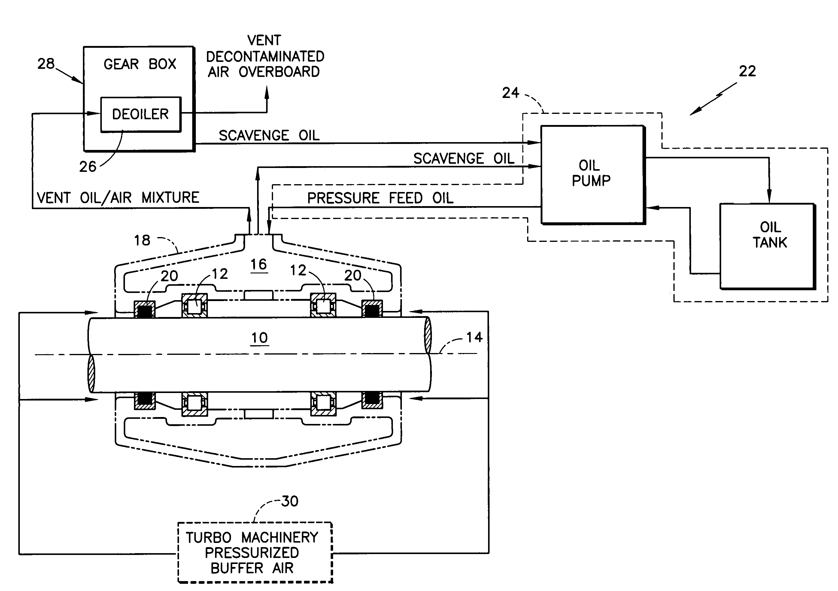
[0020]Referring to FIG. 1, a turbine engine shaft 10 is supported from the nonrotatable structure of the engine by bearings 12 so that the shaft is rotatable about a centerline axis 14. The bearings are enclosed in a bearing compartment 16 bounded by a compartment housing 18 and by the shaft. Seals 20 segregate the compartment from its immediate surroundings. These seals are imperfect, i.e. they allow some leakage, despite being designed and manufactured according to exacting standards.

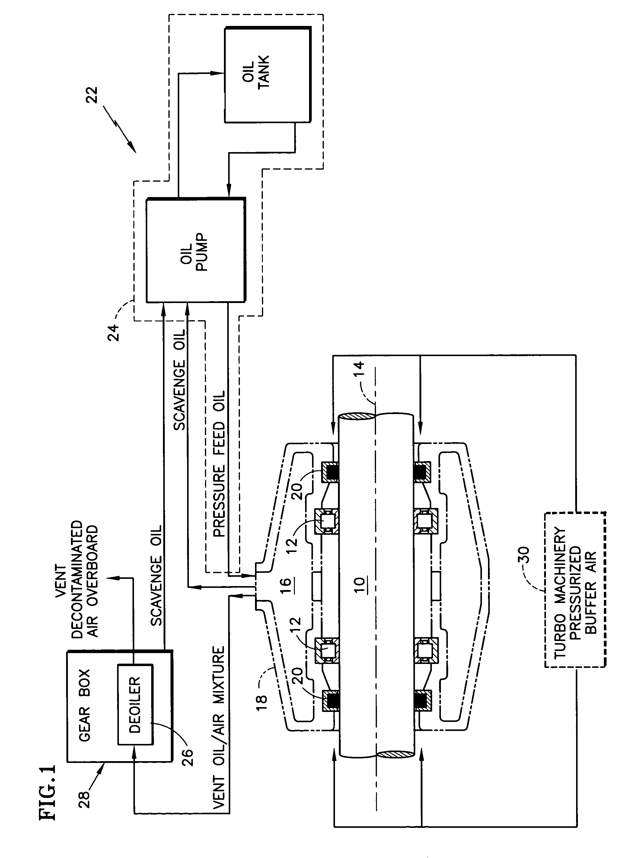
[0021]A lubrication system22 includes a lubricant supply subsystem 24 comprising a pump, an oil tank, supply lines, and other components not illustrated. The supply subsystem introduces oil into the bearing compartment. The lubrication system also includes a deoiler 26, which is typically enclosed inside an engine gearbox 28. The lubrication system also includes a buffering subsystem 30, which extracts pressurized air, referred to as buffer air, from the engine's working medium flowpath and delivers i...


PUM

PropertyMeasurementUnit
nonzero angleaaaaaaaaaa
angleaaaaaaaaaa
pressureaaaaaaaaaa

Abstract

A deoiler 26 for separating oil from air contaminated with the oil has at least one separator for separating the oil from the air and also has a source of suction for reducing air pressure at the source of the air. In an exemplary embodiment, the deoiler 26 creates the suction at a first operating condition, but acts as a restrictor at a second operating condition. A deoiling method according to the invention creates suction at a first operating condition to reduce the air pressure at the source of the oil-contaminated air, establishes a flow restriction at a second operating condition to pressurize the air source, and encourages oil to separate from the air at both operating conditions. When used as a component of a turbine engine lubrication system 22, the source of contaminated air may be a buffered bearing compartment 16. The inventive deoiler ensures a positive pressure difference across the bearing compartment seals 20 at the engine's idle power setting without requiring the idle setting to be undesirably high, and without requiring the use of buffer air whose pressure at higher engine power is high enough to be detrimental. In an exemplary embodiment, the deoiler pressurizes the bearing compartment at higher power settings to resist excessive buffer air infiltration into the bearing compartment.

Description

TECHNICAL FIELD[0001]This invention relates to lubrication system deoilers of the type useful in an aircraft gas turbine engine, and particularly to a deoiler that establishes a desirable pressure difference across the engine bearing compartment seals irrespective of engine power.BACKGROUND OF THE INVENTION[0002]A typical, conventional gas turbine engine includes one or more multi-stage compressors, a combustor, and one or more turbines. An annular working medium flowpath extends through the compressors, combustor and turbines. A drive shaft connects each turbine to an associated compressor. At least one of the drive shafts is supported from the nonrotatable structure of the engine by bearings, which are enclosed in a bearing compartment. A lubrication system introduces oil or other lubricant into the bearing compartment to lubricate and cool the bearings, and also reconditions the oil for re-use. Bearing compartment seals help prevent oil leakage out of the compartment by segregati...

Claims


Application Information

Patent Timeline
Patent Type & Authority Patents(United States)
IPC IPC(8): F02C7/06F01D25/18B01D45/14F01D11/04F04D25/04F04D29/063
CPCB01D45/14F01D11/04F01D25/18F02C7/06F04D25/04F04D29/063F01M2013/0422F05D2240/14F05D2240/55F05D2240/70F05D2260/6022
Inventor SHERIDAN, WILLIAM G.GLAHN, J. AXELTHORESEN, JAMES T.SPIRES, LARRY W.DONG, YUANMCCUTCHAN, SEAN P.
Owner RTX CORP
Why Eureka
Try Eureka