Gas cooling methods for high pressure fuel storage tanks on vehicles powered by compressed natural gas or hydrogen

a fuel storage tank and high-pressure technology, which is applied in the direction of electrochemical generators, container discharging methods, packaged goods types, etc., can solve the problems of inability to obtain a full refilling tank pressure without pressure compensation, increase and lower the internal tank temperature, so as to increase the refueling efficiency of the hydrogen refilling system and minimize energy loss. , the effect of reducing the heating of the tank

Active Publication Date: 2008-05-27
HONDA MOTOR CO LTD
View PDF5 Cites 56 Cited by
  • Summary
  • Abstract
  • Description
  • Claims
  • Application Information

AI Technical Summary

Benefits of technology

[0006]It is an object of the present invention to minimize energy loss and increase refueling efficiency in hydrogen refilling systems when factored into the overall energy efficiency of an infrastructure of high pressure gas powered vehicles and fuel depots for the consumer dispensation of high pressure fuel. Typically, each time a vehicle is refueled with hydrogen, mechanical compression transforms into thermal energy and results in the heating of refueled gas in the tank, hence, it is an object of the invention to minimize tank heating and to increase the efficiency and refueling capacity of an on board fuel storage tank in a hydrogen powered motor vehicle. It is an object of the invention to minimize high pressure gas tank heating and to increase the efficiency and refueling capacity of an on board fuel storage tank in high pressure gas powered motor vehicles. It is an object of the invention to provide a system that can remove the compression heat resulting from refueling an on board tank during high pressure refueling. An avoidance of secondary gas cooling pretreatment and / or pressure overfill, a speedier refueling time, increased refueling efficiency, and an extension of overall vehicle range will result. Improved tank capacity per unit volume is achieved during refilling, particularly where nominal refill pressure is in the range of 10,000 psi or greater.SUMMARY OF THE INVENTION
[0007]The invention provides a system that can remove the heat of compression resulting from the high pressure refueling of an on board vehicle tank. Refueling time will decrease and refueling efficiency and overall vehicle range will increase as a result of the improved tank capacity per unit volume achieved by the tank gas cooling system described herein. In accordance with the present invention, effective reduction of fuel tank heating during the refueling process is provided by systems for heat evacuation in which a tank interior heat absorber is interconnected with an external heat radiator, thereby collecting interior tank heat and radiating the absorbed heat into the ambient atmosphere or other system appropriate for the use, radiation, absorption, or disposal of the collected heat of high pressure refueling. At a high pressure hydrogen or compressed natural gas vehicle refuel depot, the thermal energy (heat) generated by from the high flow rate of the high pressure refueling gas is evacuated from the on board fuel tank[s] of consumer vehicles eliminating the need for refueling pre treatments such as a slow fill, secondary precooling, and pressure overfill otherwise used to achieve a full vehicle tank refill. In an example, a high pressure fuel depot refilling line is operatively interconnected to an on board vehicle tank having a gas flow circuit wherein the refuel gas itself is circulated within the on board tank to absorb the compression heat of refueling and then to an external radiator before being released into the tank.
[0008]The invention provides a system that can remove the compression heat resulting from refueling an on board tank during high pressure refueling, particularly when nominal refill pressure is in the optimum design range of 10,000 psi or greater. Reduction of fuel tank heating during the refueling process is effected by a heat evacuation system in which an interior tank heat absorber is interconnected with an external heat radiator; the interior absorber collects tank heat resulting from high pressure compression and radiates the absorbed heat into the ambient atmosphere or other vehicle system appropriate for the disposal of collected heat. In a variation utilizing the refuel gas as its own heat sink, a tube circulating the high pressure refueling gas from the consumer pump at the refill depot is circulated in a circuit from within the tank interior to an external radiator where collected heat associated with the refueling process is radiated to or absorbed by the external environment before the refueling gas enters the tank. In this manner; the intrinsic energy from the high flow rate of the high pressure, 10,000 psi or greater, refueling gas is utilized to power the heat evacuation system. Time and energy consuming techniques such as a slow fill, secondary precooling, and pressure overfill are not necessary. In brief, the invention provides a system for reducing the energy and for reducing the time required to refill on board tanks on a vehicle from a high pressure fuel depot refilling line operatively interconnected to the tank wherein the refuel gas itself is circulated within the on board tank to absorb the compression heat of refueling, and the heat thereby absorbed is radiated from the refueling circuit to an external environment before the fuel reaches the tank such that a close to optimum refill of the tank is achieved.

Problems solved by technology

Conventionally, it is not possible to obtain a full refill tank pressure without pressure compensation during the course of refueling; namely, the charge of fuel pressure input into and stored in the tank must be, at refill, initially in excess of the tank design pressure.
In one response to the overfill dilemma, a slower flow rate may be used during refill, which will result in a lower internal tank temperature, and higher pressure, and increased capacity over time.
An undesirable consequence of a slower flow rate during refueling to avoid heat build up is self evident—a longer refueling time.
Another solution proposes to cool the station fuel gas before refueling; cooling, however, requires substantial energy, thereby reducing the overall efficiency of a hydrogen economy.
A pressure overfill as an option likewise requires additional energy expense where additional gas compression is involved and further increases the heat generated in the tank as a result of high pressure compression during the refill process.
In any case, secondary treatment of the refill gas is generally unnecessary when tank fill pressures are at 5000 psi or lower.

Method used


Image

  • Gas cooling methods for high pressure fuel storage tanks on vehicles powered by compressed natural gas or hydrogen
  • Gas cooling methods for high pressure fuel storage tanks on vehicles powered by compressed natural gas or hydrogen
  • Gas cooling methods for high pressure fuel storage tanks on vehicles powered by compressed natural gas or hydrogen

Examples


Embodiment Construction

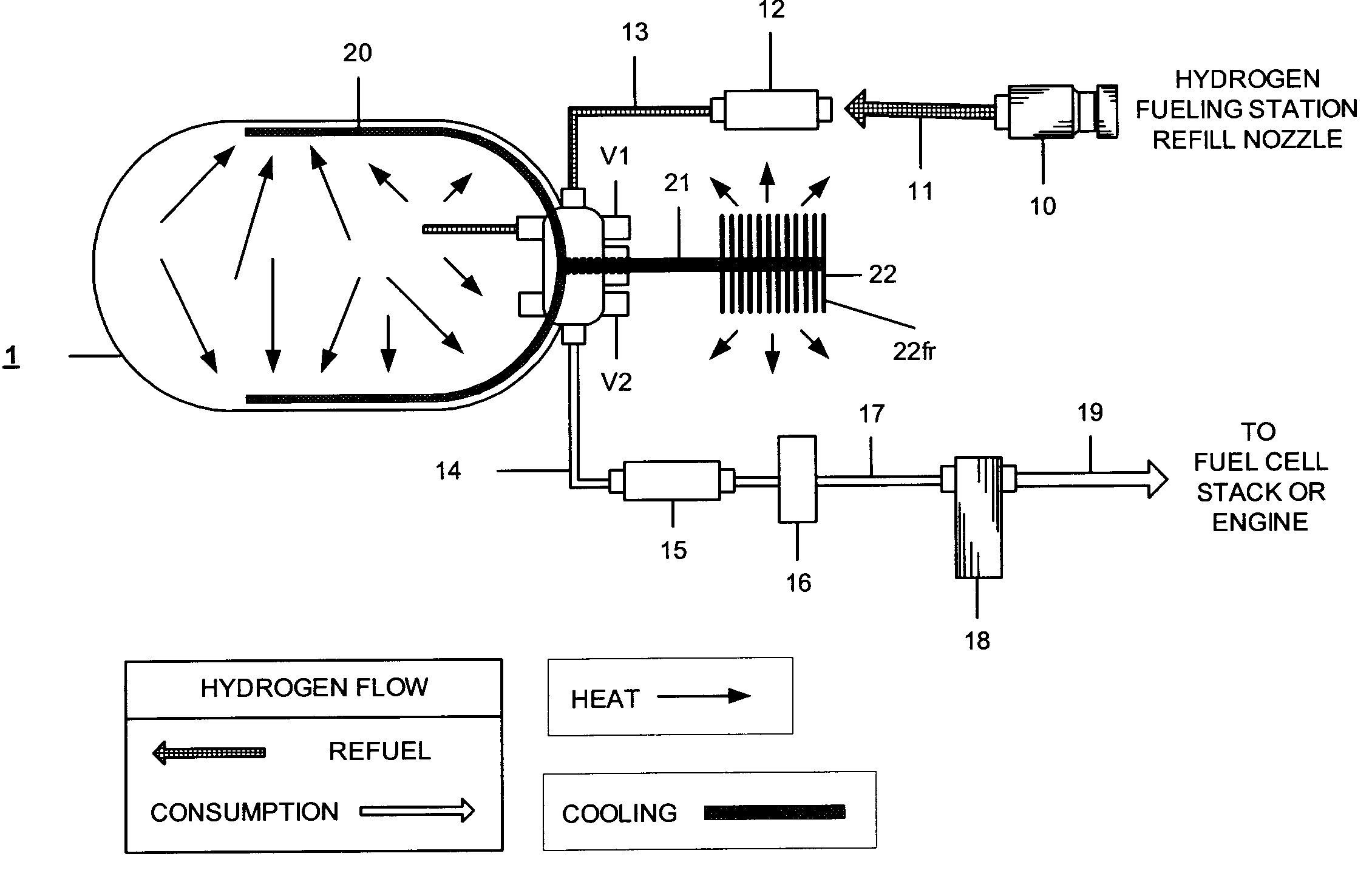
[0017]The system of the invention increases the refueling energy efficiency of hydrogen powered vehicles by withdrawing the heat of refilling compression from the high pressure gas introduced into on board tanks and by eliminating the need for a slow fill, a pressure overfill and / or refueling station precooling of the gas. Less energy is required to completely refill on board vehicle tanks at a refueling depot. The invention reduces the energy required to recharge the on board vehicle tanks with high pressure gas at the station to return the tanks to a full optimal state in the process of refueling. As a result, overall infrastructure energy requirements are reduced, vehicle mileage range is increased, reducing the need for short interval refills, and enhancing consumer satisfaction. The energy and time required to refill on board tanks on a vehicle from a high pressure fuel depot refilling line is reduced by the invention. A cooling circuit coil is disposed within the on board tank...


PUM

PropertyMeasurementUnit
pressuresaaaaaaaaaa
pressuresaaaaaaaaaa
pressuresaaaaaaaaaa

Abstract

At a high pressure refuel depot that dispenses high pressure hydrogen or compressed natural gas to vehicles, the thermal energy (heat) generated by the high flow rate of the high pressure refueling gas is evacuated from the on board fuel tank[s] of vehicles eliminating the need for refueling pre treatments such as a slow fill, secondary precooling, and pressure overfill otherwise used to achieve a full vehicle tank refill. In an example, a high pressure fuel depot refilling line is operatively interconnected to an on board vehicle tank having a gas flow circuit wherein the refuel gas itself is circulated within the on board tank to absorb the compression heat of refueling and then to an external radiator before being released into the tank.

Description

RELATED APPLICATIONS[0001]This application is related to and claims all benefits under 35 U.S.C. §119(e) of my earlier U.S. Provisional Patent Application Ser. No. 60 / 673,175 filed on Apr. 20, 2005, entitled “Gas Cooling Methods for High Pressure Storage Cylinder Fuel Tanks on Vehicles Powered by Compressed Natural Gas or Hydrogen.”FIELD OF THE INVENTION[0002]The present invention relates to a system for efficiently refueling high pressure, on board, vehicle gas fuel tanks for hydrogen gas and compressed natural gas at a refueling station where high capacity, high pressure fuel storage tanks provide the fuel to the vehicle through a consumer dispensing means.BACKGROUND OF THE INVENTION[0003]When high pressure gases, such as hydrogen (“H2”) and compressed natural gas (CNG) are used as fuels in motor vehicles, a fuel depot infrastructure for efficient consumer refueling of the vehicles must also be developed. Typically, in the use of hydrogen gas to power fuel cells, or in the use of ...

Claims


Application Information

Patent Timeline
Patent Type & Authority Patents(United States)
IPC IPC(8): B65B1/00
CPCB60K15/00F17C5/007F17C13/001F17C2270/0184F17C2270/0178Y02E60/321F17C2201/0109F17C2203/0604F17C2203/0648F17C2203/0656F17C2203/066F17C2205/0323F17C2205/0338F17C2221/012F17C2221/033F17C2223/036F17C2227/0341F17C2227/0346F17C2227/0379F17C2227/0383F17C2227/04F17C2250/043F17C2250/0439F17C2250/0626F17C2250/0631F17C2270/0139F17C2270/0168B60K2015/03414Y02E60/32
Inventor HANDA, KIYOSHI
Owner HONDA MOTOR CO LTD
Why Eureka
Try Eureka