Chamfering cutting tool or grinding wheel and method of making and use thereof

a grinding wheel and cutting tool technology, applied in the direction of gear teeth, manufacturing tools, manufacturing apparatus, etc., can solve the problems of stress risers, premature failure of gear wheels or other parts associated with slots or gear teeth, and undesirable edges on workpieces

Inactive Publication Date: 2008-05-27
ARVIN JOSEPH L
View PDF12 Cites 27 Cited by
  • Summary
  • Abstract
  • Description
  • Claims
  • Application Information

AI Technical Summary

Benefits of technology

[0015]The inventive method provides a cutter or grinding wheel capable of producing a chamfered end on both a front face and a back face of a gear. The disc or ball type cutter or grinding wheel is mounted on a spindle which is held and positioned by a gear grinding machine, cutter grinder, conventional or CNC machine tool, or via a robotic arm. The gear or work piece is held in a CNC indexable chuck and the cutter or wheel is used to chamfer one gear tooth or one slot at a time in a single pass. The work holding chuck then indexes the work piece, thereby positioning it for the cutter or wheel to chamfer the next tooth or slot in a subsequent pass. A significant advantage of the invention is that the cutter or wheel produces a uniform chamfer with one feed of the cutter or wheel, eliminating time consuming hand operations, scrap, rework and the operator breathing the air borne particles resulting form the hand chamfering operations that are entrained in the ambient air.
[0016]A significant advantage of this invention is that the cutter or grinding wheel produces a uniform chamfer with one in feed of the cutter or wheel. For complex, non-uniform work pieces like dove tail slots, the cutter or grinding wheel may require two to three passes to provide a chamfer to the entire slot periphery.

Problems solved by technology

It is generally undesirable to leave sharp edges on the work piece, because sharp edges and / or a non-uniform chamfer at the edges of the work piece causes stress risers or points on the work piece during its functional operation.
Moreover, sharp edges or non-uniform chamfered work pieces can cause stress cracks leading to premature failure of the gear wheel or other part associated with the slot or gear tooth.
Especially in aerospace applications, such as helicopters and airplanes, this can result in substantial risk of loss of human life.
Both of these methods have been found to be unsatisfactory, however, due to the non-uniform chamfering produced by the Gratomat Deburring machine and the labor and wastage costs associated with contour milling.
Moreover, hand chamfering operations using a hand grinder, even by a skilled operator, result in slight imperfections in the uniformity of the chamfer, which produce asymmetric chamfers on the work piece that can and do develop into stress cracks, eventually leading to premature failure of the gearbox or other equipment having the slotted element.
These alternative deburring methods are for the most part inefficient, mostly unproductive, and unnecessarily costly because of personnel and labor costs.
The problems noted with hand chamfering typically result in up to 10% scrap and substantial rework, up to 30%, of hand chamfered products.
Nevertheless, the hob chamfering process of the '093 patent has limitations in use, because it is not possible to utilize hob chamfering for certain applications, for example, non-standard gear teeth configurations, keyway or dovetail slots, or for internally oriented gear teeth for an internal gear wheel.
In such cases, it becomes more difficult or impossible to control the movement of an automated arm to obtain the correct orientation of the types of chamfer hobs or contour milling machines heretofore used by the prior art devices because the range of motion is limited by the dimensions of the slots and the size of the hob providing the chamfer.

Method used


Image

  • Chamfering cutting tool or grinding wheel and method of making and use thereof
  • Chamfering cutting tool or grinding wheel and method of making and use thereof
  • Chamfering cutting tool or grinding wheel and method of making and use thereof

Examples


Embodiment Construction

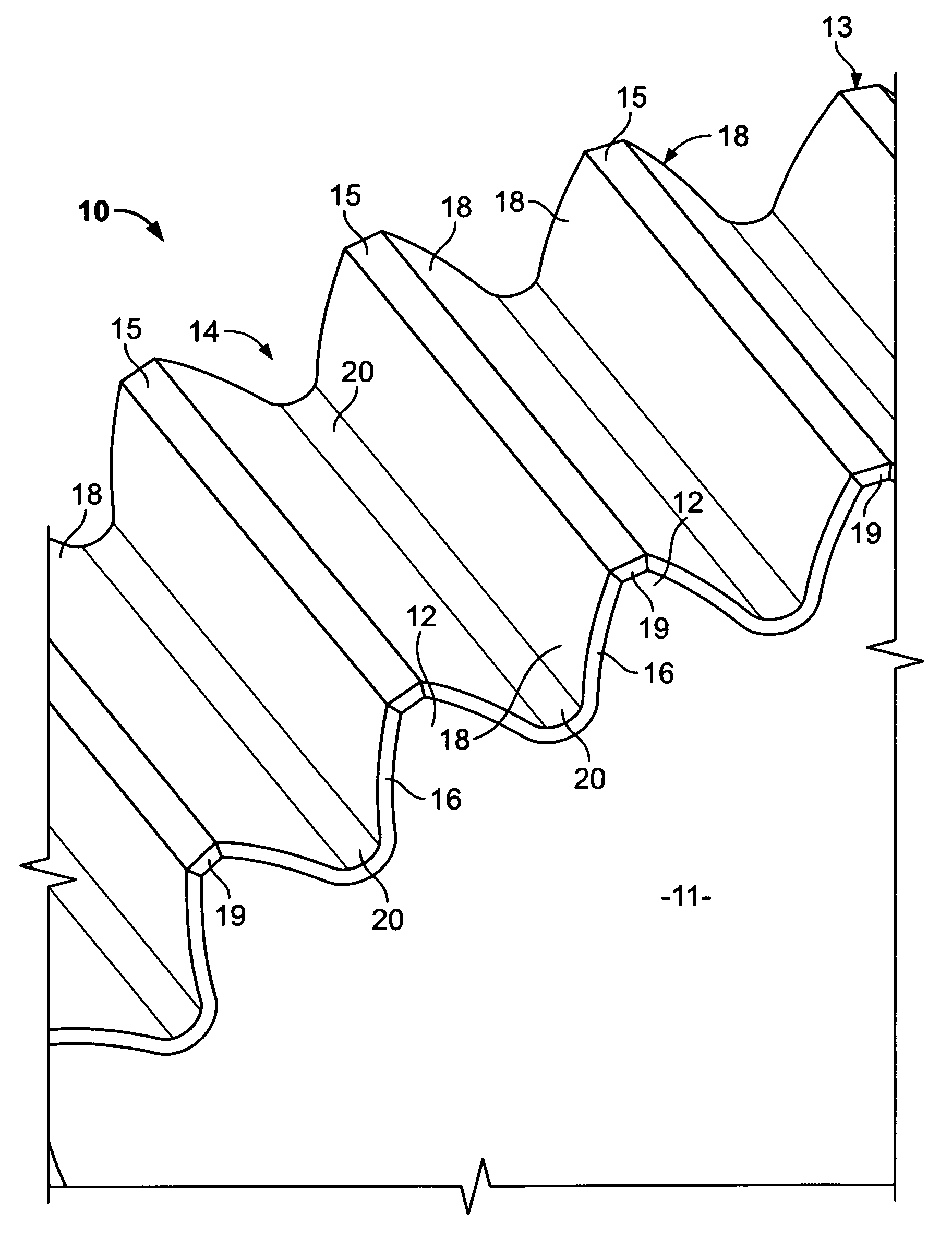
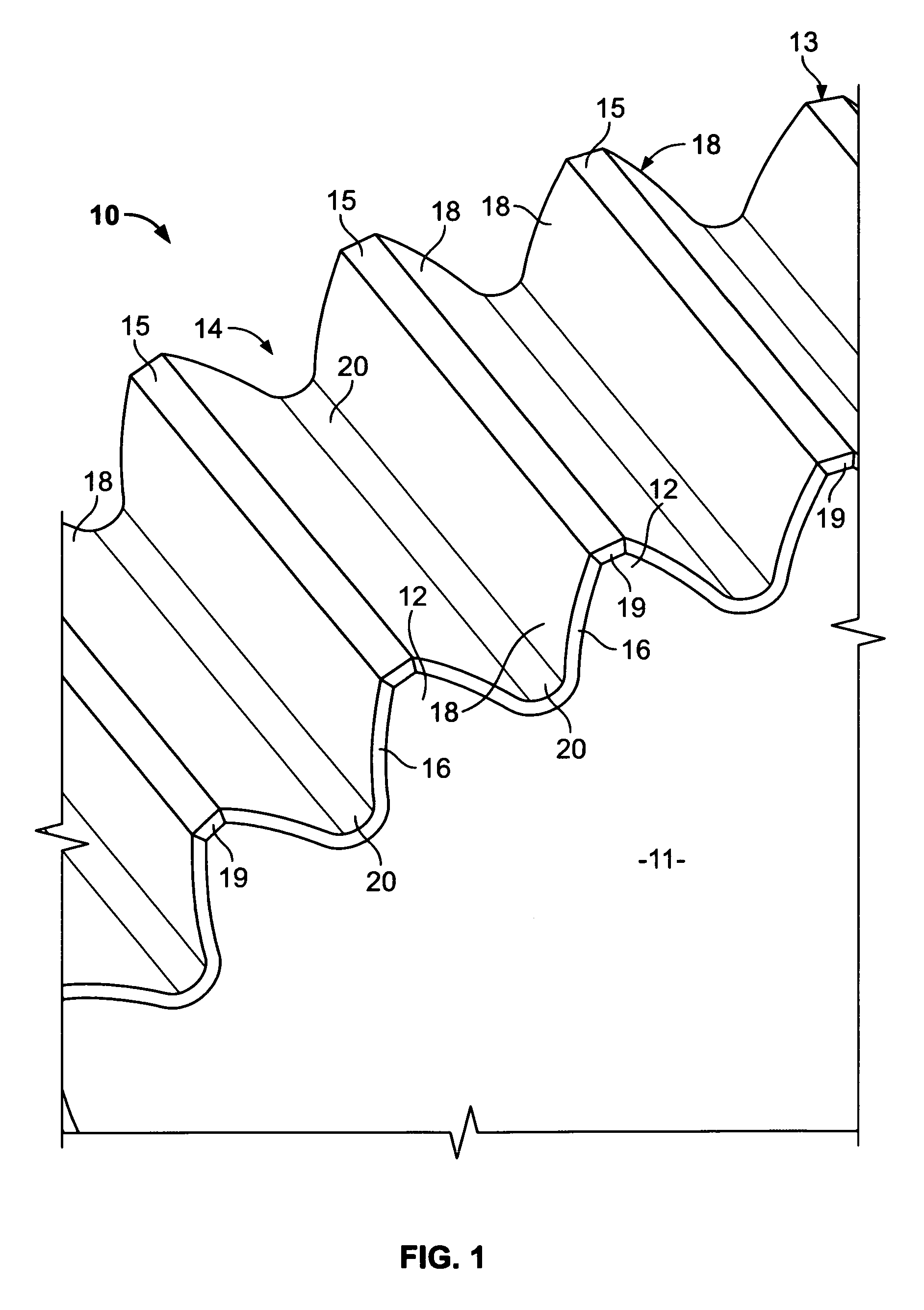
[0028]Referring now to FIG. 1, a perspective, detail view of an external gear wheel or ring 10 having gear teeth 12 defining slots 14 such that the gear wheel 10 may be suitable for various uses in a gear assembly. The present invention is capable of use with other types of gear wheels, as will be described in reference to the separate drawing figures, but the embodiment of gear wheel 10 shown in FIG. 1 is the simplest of the configurations and will be discussed first to provide a basis for expanding the scope of use of the invention to additional, more complex, arrangements.

[0029]Each of the slots 14 are defined by adjacent gear teeth 12, and the slots 14 and gear teeth 12 extend through the thickness of the gear wheel 10. The slots 14 are normally cut in a depth direction of the gear wheel 10 from a front face 11 all through the thickness of the gear wheel to a rear or back face 13. The slots 14 are normally cut by a hob (not shown) in a pass along the outer circumferential edge s...


PUM

PropertyMeasurementUnit
chamfer angleaaaaaaaaaa

Abstract

A work piece having edges comprising teeth, slots, dovetail, keyway or other irregularly shaped artifacts, can be provided with a uniform chamfer around the periphery of the work piece by bringing a grinding wheel or cutter in one single down feed at indexed intervals. The shape or profile of the grinding wheel or cutter is formed from an algorithm depending on the shape and dimensions of the work piece artifacts, such as gear teeth, etc., to provide the uniform chamfer at each slot of, for example, an internal or external gear wheel. A method of providing such a chamfer on irregularly shaped artifacts comprises forming a gear grinding wheel from the dimensions of the desired chamfer, and providing a chamfering tool or grinding wheel in accordance with an algorithm desired for the required chamfer, then bringing the gear chamfering tool in proximity to, and in contact with the edges of the work piece so as to produce a uniform chamfer on the sides and back edge. The method may include a step of moving of the cutter or grinding wheel from one side to another and tilting the cutter or grinding wheel to chamfer the back side.

Description

CROSS REFERENCE TO RELATED APPLICATIONS[0001]This is a continuation-in-part application of U.S. Ser. No. 11 / 514,492, filed on Sep. 2, 2006, now abandoned which is a continuation-in-part application of U.S. Provisional Patent Application Ser. No. 60 / 713,975, filed on Sep. 2, 2005, which is a continuation-in-part application of U.S. Ser. No. 10 / 310,417, filed Dec. 5, 2002, issued on Sep. 6, 2005 as U.S. Pat. No. 6,939,093, the specifications of which in their entirety are incorporated herein by reference.BACKGROUND OF THE INVENTION[0002]1. Field of the Invention[0003]This invention relates generally to the deburring and precise chamfering of slots used in conjunction with gear teeth, spline teeth, dovetail slots, keyways, and other non-symmetrical shapes, internal or external, and more specifically, to the deburring and precise chamfering of gear teeth using a grinding wheel or cutter to provide a precise deburring or chamfering operation in a single feed or pass.[0004]2. Background A...

Claims


Application Information

Patent Timeline
Patent Type & Authority Patents(United States)
IPC IPC(8): B23F5/22
CPCB23F19/12B23F21/02Y10T409/10159Y10T409/101749
Inventor ARVIN, JOSEPH L.
Owner ARVIN JOSEPH L
Why Eureka
Try Eureka