Marine propulsion shift control

a shift control and propulsion technology, applied in marine propulsion, propulsive elements, vessel construction, etc., can solve the problems of engine stall, sudden increase in engine load, engine stall, etc., to avoid engine stall, reduce clutch wear, the effect of reducing the effect of wear

Active Publication Date: 2008-05-27
STURDY TRUCK EQUIP
View PDF28 Cites 16 Cited by
  • Summary
  • Abstract
  • Description
  • Claims
  • Application Information

AI Technical Summary

Benefits of technology

[0009]In accordance with a further aspect of the invention, there is provided a marine propulsion system including an engine, a transmission coupled to the engine by a clutch to permit selective engagement and disengagement with the engine, and a propulsion unit coupled to the transmission. A controller is provided in communication with the engine and the transmission. An operator input device includes a position sensor that is coupled to the controller to permit an operator to input a transmission shift request. The transmission further includes a transmission shift actuator coupled to the controller to receive shift commands from the controller, and also includes a transmission fluid pressure sensor coupled to the controller. The engine includes an engine speed actuator coupled to the controller to receive speed commands from the controller, and further includes an engine speed sensor coupled to the controller. In response to receiving a transmission shift request from the operator input device, the controller determines one or more shift commands using signals from the sensors and sends the shift command(s) to the transmission shift actuator to thereby provide a controlled shifting of the transmission in a manner that reduces wear to the clutch and avoids engine stalls.

Problems solved by technology

Engine stalling is a problem sometimes encountered when operating a marine vessel, and often this occurs when the vessel is moving in one direction at high speed and the operator suddenly shifts the transmission into the opposite gear.
Reversing the transmission under these circumstances, however, places a sudden increased load on the engine because of the drag load on the propeller.
As a result, the engine is often unable to overcome the sudden increased load and, therefore, the engine stalls.
Another problem can arise when a pilot attempts to avoid the engine stalling problem.
Racing the engine, however, can lead to transmission clutch damage caused by excessive engine speed prior to full engagement of the transmission clutch to the engine.
Exceeding the maximum acceptable engine speed during a shift tends to result in excessive clutch temperatures and possibly clutch failure.
This method is only effective under specific conditions, such as where the drag load on the propeller decreases by a sufficient amount during the time delay such that the engine can overcome the sudden increased load without stalling.
In some instances, however, this method may be ineffective because the shift is not delayed long enough and the engine stalls, or because the delay is too long resulting in an unnecessarily long shift delay.

Method used


Image

  • Marine propulsion shift control
  • Marine propulsion shift control
  • Marine propulsion shift control

Examples


Embodiment Construction

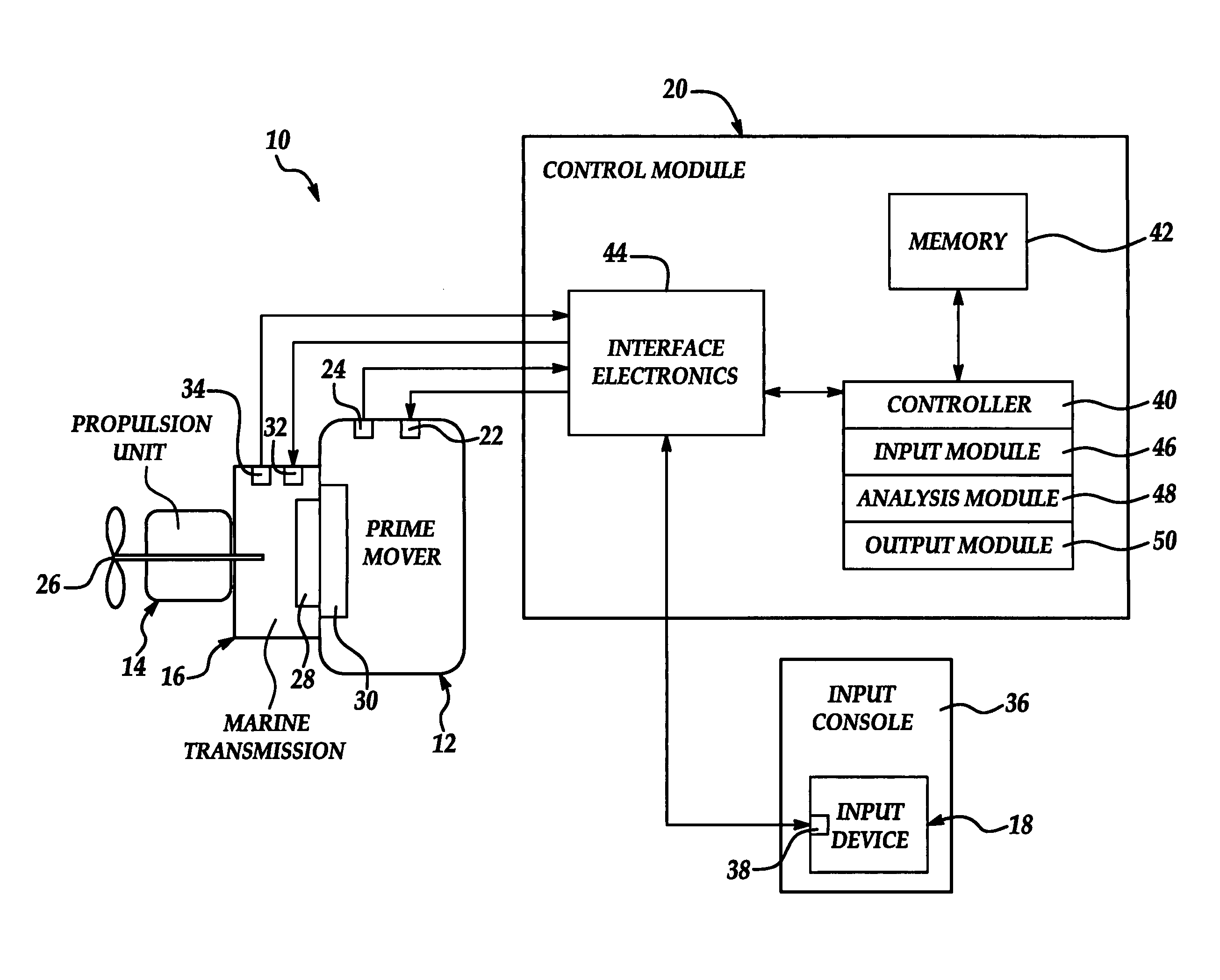
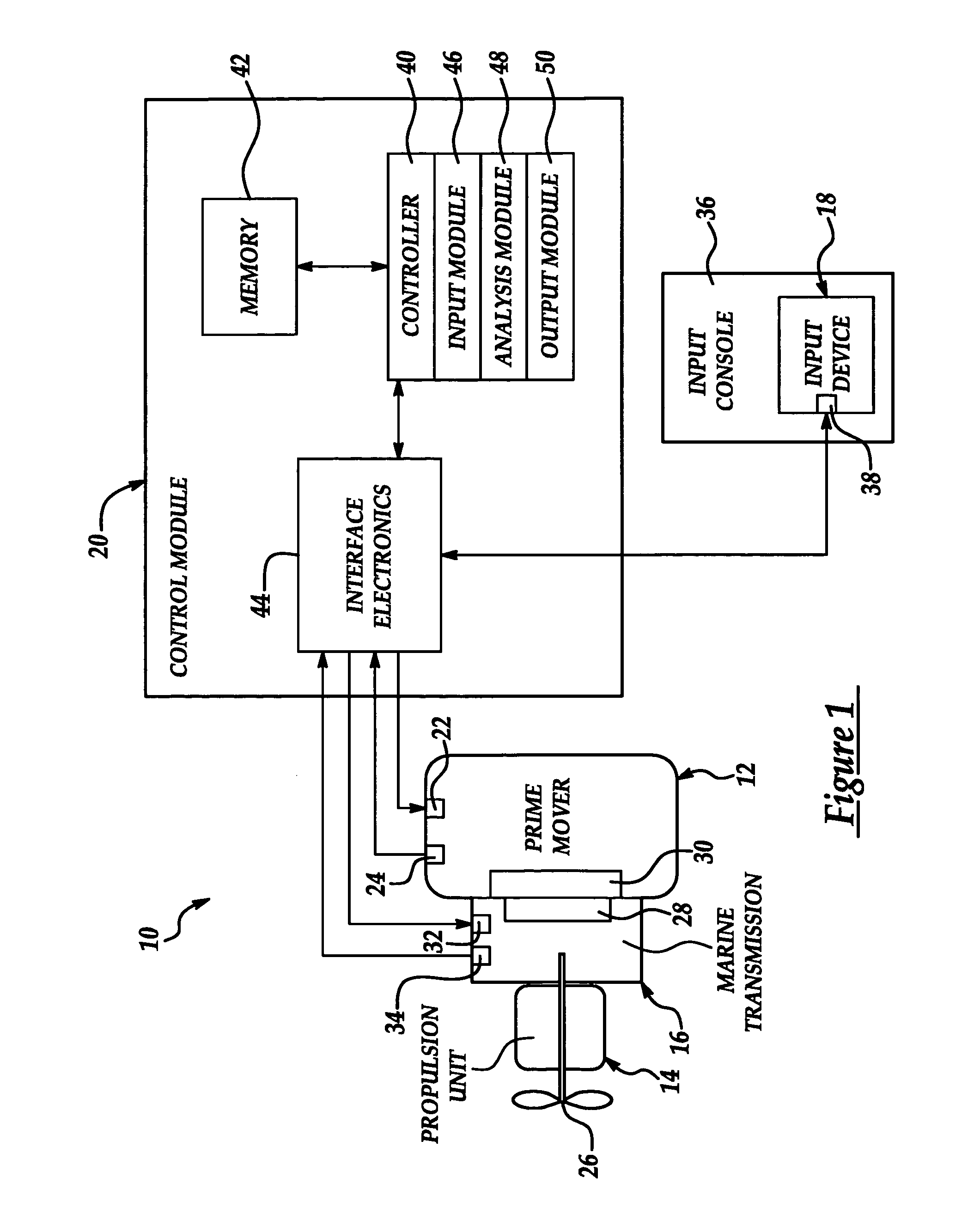
[0014]FIG. 1 illustrates a block diagram of a marine propulsion system 10 according to an embodiment of the present invention. The marine propulsion system 10 generally resides within a marine vessel (not shown) and includes the following main elements: a prime mover (engine) 12 for powering the vessel, a propulsion unit 14 for propelling the vessel, a marine transmission 16 for converting the output of the engine 12 into an input to the propulsion unit 14, a throttle control lever 18 or other manual input device used by the pilot to control transmission shifting and engine speed, and a control module 20 for controlling the engine 12 and transmission 16 in response to the manual input from the pilot.

[0015]The engine 12 is mounted to the vessel as is well-known in the art and, as used herein, the term “engine” means an internal combustion engine, a turbine engine, electric motor, and the like. For example, an internal combustion engine provides rotational power from a crankshaft (not...


PUM


Abstract

A marine propulsion system that utilizes a transmission shift sequence to control shifting of the propulsion system transmission between forward and reverse gears. The marine propulsion system includes a controller that executes the transmission shift sequence using engine speed and transmission fluid pressure signals to determine the timing of various steps in the shift sequence. The controller is connected to a shift actuator for the transmission and to an engine speed throttle to thereby control transmission shifting and engine speed as a part of the transmission shift sequence. By monitoring engine speed and transmission fluid pressure, and by controlling transmission shifting and engine speed settings, the transmission shift sequence can provide the operator with the ability to carry out quick shifts that will neither stall the engine nor damage the transmission clutch.

Description

CROSS REFERENCE TO RELATED APPLICATION[0001]This application claims the benefit of the priority of U.S. Provisional Application Ser. No. 60 / 480,429, filed Jun. 20, 2003, the entire contents of which are hereby incorporated by reference.TECHNICAL FIELD[0002]The present invention relates to a method and apparatus for controlling transmission shifts in a marine propulsion system.BACKGROUND OF THE INVENTION[0003]Marine vessels in use today use marine propulsion systems that typically include the following sub-systems: an engine to provide power, a transmission to transfer drive power to a propeller, and a control system to provide control of engine speed and transmission engagement. An operator or pilot of the vessel nominally has control of the engine speed and transmission shifting through one or more operator controls. Using these operator controls, the transmission can be shifted between forward and reverse, usually through a neutral (transmission disengaged) position, and the engin...

Claims


Application Information

Patent Timeline
Patent Type & Authority Patents(United States)
IPC IPC(8): B63H21/21B63B23/08B63B23/30
CPCB63H21/22B63H23/30Y10T477/688
Inventor STURDY, DAVID RONALDGALLAHER, JAMES DEREKMEEK, OSCAR LEE
Owner STURDY TRUCK EQUIP
Why Eureka
Try Eureka