Fuel cell and small electric equipment

a fuel cell and electric equipment technology, applied in the field of fuel cells, can solve the problems of large fuel cell area, inability to improve the power generation efficiency of the fuel cell, and difficulty in accurately forming a fine structure for oxidizer and fuel passages, etc., to achieve easy manufacturing, increase the area for the reaction of fuel cells, and excellent buckling strength

Inactive Publication Date: 2008-05-27
CANON KK
View PDF9 Cites 0 Cited by
  • Summary
  • Abstract
  • Description
  • Claims
  • Application Information

AI Technical Summary

Benefits of technology

[0019]The electrolyte / electrode joined member in accordance with the present invention, which comprises a fuel electrode, an oxidizer electrode, and an electrolyte membrane, is characterized in that a plurality of spacers are provided dispersedly to be in contact with at least a surface on the oxidizer electrode side of the electrolyte / electrode joined member. At the oxidizer electrode, it is important to supply an oxidizing gas onto the electrolyte membrane and to remove generated water, and thus it is important to increase the area for the reaction thereof. In the present invention, since a plurality of small spacers, which are different from a conventional integral spacer that is complex and thick, are provided dispersedly, flow paths can easily be secured to enable fuel cells to be easily manufactured.
[0020]In particular, it is particularly preferable that the spacers each have an approximately spherical shape. In this case, there are advantages that the spacers come into contact with the electrolyte / electrode joined member in a small area and have an excellent buckling strength because of the spherical shape thereof, and that since the degree of freedom of positional accuracy when disposed is high, the assembly cost of the fuel cell is low. Further, disposing the spherical spacers can easily secure flow path spaces for fuel and an oxidizer, which can eliminate a conventional, difficult step of forming a flow path structure on a separator. In the light of the above description, it is also effective to further dispose the spherical spacers on a surface on the fuel electrode side of the electrolyte / electrode joined member. Moreover, the spherical spacers have an economical effect that they can be obtained at a low cost when spherical spacers generally used in a liquid crystal display are employed as such.
[0021]In the present invention, it is preferable that the surface of the spherical spacer has a hydrophilicity higher than that of the surface of the electrolyte / electrode joined member. As described above, the power generation will form water at the oxidizer electrode, and it is effective to remove the water to efficiently continue the reaction. Here, a surface having a higher hydrophilicity is advantageous in that, when water is in contact with a more hydrophilic surface and with a less hydrophilic surface, the contact angle of water with the more hydrophilic surface is smaller than that with the less hydrophilic surface, whereby the water will move to the more hydrophilic surface side by the effect of surface tension. When adopting this preferable feature of the present invention, since the more strongly hydrophilic surface of the spacer will increase the area of the surface that absorbs the generated water from the surface of the electrolyte / electrode joined member and keep and vaporize the water, the power generating efficiency of the fuel cell can be improved.
[0022]When the fuel cell of the present invention has an electrode / electrolyte membrane stack structure in which at least two electrolyte / electrode joined members are stacked, they are stacked such that the same kind of electrodes face each other on the oxidizer electrode side thereof through the spherical spacers. With the above arrangement, since the oxidizer electrodes face each other and the fuel electrodes face each other, a separator structure for separating gases is not necessary, so that the thickness of the electrode / electrolyte membrane stack structure can be reduced. Further, the voltage / current of the output power can be freely controlled by connecting the electrolyte / electrode joined members in series or in parallel in a predetermined fashion.

Problems solved by technology

H04-25673 described above has a problem that the size of the fuel cell depends on the thickness of the separator and is large in a stack direction.
The separator merely has a role of electrically isolating upper and lower electrodes and keeping a flow path space and therefore does not improve the power generation efficiency of the fuel cell.
Further, in the fuel cell, it is very difficult to accurately form a fine structure for oxidizer and fuel passages.

Method used


Image

  • Fuel cell and small electric equipment
  • Fuel cell and small electric equipment
  • Fuel cell and small electric equipment

Examples


example 1

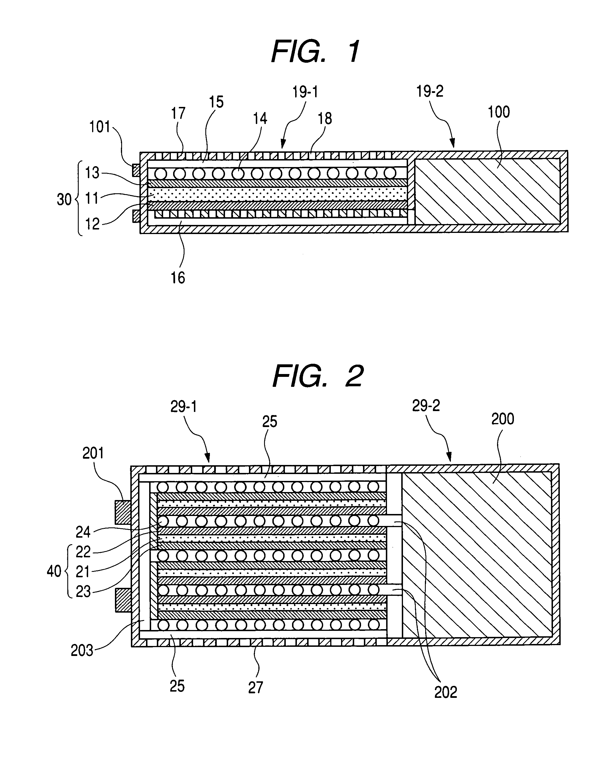
[0044]FIG. 1 shows a sectional view of a fuel cell as a first example of the present invention. The fuel cell includes at least a cell unit (fuel cell body) 19-1 having an electrolyte / electrode joined member 30, a fuel unit 19-2 for storing a fuel 100, and power taking out terminals 101.

[0045]In FIG. 1, the electrolyte / electrode joined member 30 includes an oxidizer electrode 13 having a catalyst on the upper surface of an electrolyte membrane 11 and a fuel electrode 12 having a catalyst on the lower surface thereof. The electrolyte membrane 11 is composed of, for example, a polymeric material having a protonic conductivity, specifically Nafion (trade name; produced by DuPont).

[0046]The oxidizer electrode 13 and the fuel electrode 12 are composed of, for example, carbon powder containing platinum microparticles.

[0047]The electrolyte / electrode joined member 30 has spherical bead spacers 14 on the upper surface of the oxidizer electrode 13 and a separator 16 with a fuel flow path on t...

example 2

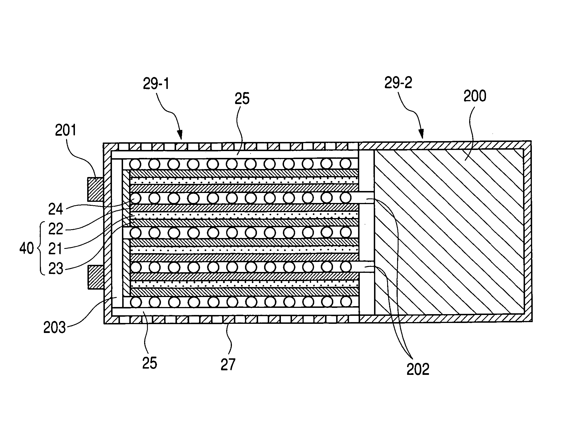
[0051]FIG. 2 shows a sectional view of a fuel cell as a second example of the present invention. The fuel cell includes at least a cell unit 29-1 having electrolyte / electrode joined members 40, a fuel unit 29-2 for storing a fuel 200, and power take-out terminals 201. The stack fuel cell of this example is characterized in that electrodes are disposed such that the same kind of electrodes (that is, fuel electrodes or oxidizer electrodes) face each other, which eliminates the necessity of a separator for separating fuel from an oxidizer. That is, oxidizing gas flow paths for flowing an oxidizing gas containing oxygen flow are formed between the electrolyte / electrode joined members where positive electrodes face each other, and fuel gas flow paths for flowing a fuel gas containing hydrogen are formed between the electrolyte / electrode joined members where negative electrodes face each other. The spherical spacers as a principal feature of the present invention support each of the elect...

example 3

[0062]FIG. 4 shows a schematic view of a digital camera using the fuel cell of the present invention.

[0063]As described above with reference to FIG. 1, a fuel cell 401 includes a cell unit having an electrolyte / electrode joined member and a fuel unit for storing a fuel, and holes formed in the surface of the fuel cell in FIG. 4 are used to take in air therethrough.

[0064]The fuel cell of the present invention is advantageous in that the output density is high; the operating temperature is as low as 100° C. or less, whereby long-term durability is expectable; it is suitable for miniaturization; and the handling is easy, and can therefore be utilized for portable equipments such as mobile phones, cameras, video cameras, notebook personal computers, and the like or as a mobile power supply. Accordingly, small electric equipments using the fuel cell of the present invention can be reduced in size / weight and can be used for a long period of time.

[0065]That is, the fuel cell of the present...


PUM

PropertyMeasurementUnit
electromotive forceaaaaaaaaaa
particle diameteraaaaaaaaaa
operating temperatureaaaaaaaaaa

Abstract

A highly efficient fuel cell is provided that can be reduced in size and provide a large electromotive force and that comprises an electrolyte / electrode joined member comprising a fuel electrode, an oxidizer electrode, and an electrolyte membrane provided between the electrodes, wherein a plurality of spacers are provided at least on a surface on the oxidizer electrode side of the electrolyte / electrode joined member.

Description

BACKGROUND OF THE INVENTION[0001]1. Field of the Invention[0002]The present invention relates to a fuel cell for generating an electric power by the reaction of fuel with an oxidizer. Further, the present invention relates to a small electric equipment using the fuel cell.[0003]2. Related Background Art[0004]A fuel cell uses an electrolyte / electrode joined member, which is composed of an electrolyte membrane sandwiched between a fuel electrode having a catalyst and an oxidizer electrode having a catalyst, as a power generation cell unit. In the electrolyte / electrode joined member, a fuel gas such as a hydrogen gas is caused to flow on the fuel electrode side while an oxidizing gas containing an oxygen gas is caused to flow on the oxidizer electrode side, and these gases electrochemically react with each other through the electrolyte membrane to provide an electromotive force to the outside. Since a single electrolyte / electrode joined member has a small electromotive force of about 0...

Claims


Application Information

Patent Timeline
Patent Type & Authority Patents(United States)
IPC IPC(8): H01M2/08H01M2/14H01M8/02H01M4/86H01M4/90H01M4/92H01M8/00H01M8/10H01M8/24
CPCH01M8/0247H01M8/1002H01M8/241H01M4/8605H01M4/90H01M4/92H01M2250/30Y02E60/521Y02B90/18H01M8/1007Y02B90/10Y02E60/50
Inventor IKEDA, SOTOMITSU
Owner CANON KK
Why Eureka
Try Eureka