Artificial dielectric antenna elements

Inactive Publication Date: 2008-05-27
LOCKHEED MARTIN CORP
View PDF16 Cites 87 Cited by
  • Summary
  • Abstract
  • Description
  • Claims
  • Application Information

AI Technical Summary

Benefits of technology

[0006]In accordance with the present invention, antennas can be loaded with an artificial dielectric antenna structure to improve radiation performance and frequency bandwidth. The artificial dielectric is implemented as a multi-sandwich structure with alternating layers of materials with higher and lower dielectric constants. The layered configuration of the artificial dielectric antenna structure allows for overall dielectric constants below 2

Problems solved by technology

However, several drawbacks offset the advantages of dielectric loading.
First, dielectric loading can cause increased insertion loss, degrading the strength of a signal.
Second, dielectric loading increas

Method used


Image

  • Artificial dielectric antenna elements
  • Artificial dielectric antenna elements
  • Artificial dielectric antenna elements

Examples


Embodiment Construction

[0022]In the following detailed description, numerous specific details are set forth to provide a full understanding of the present invention. It will be obvious, however, to one ordinarily skilled in the art that the present invention may be practiced without some of these specific details. In other instances, well-known structures and techniques have not been shown in detail not to obscure the present invention.

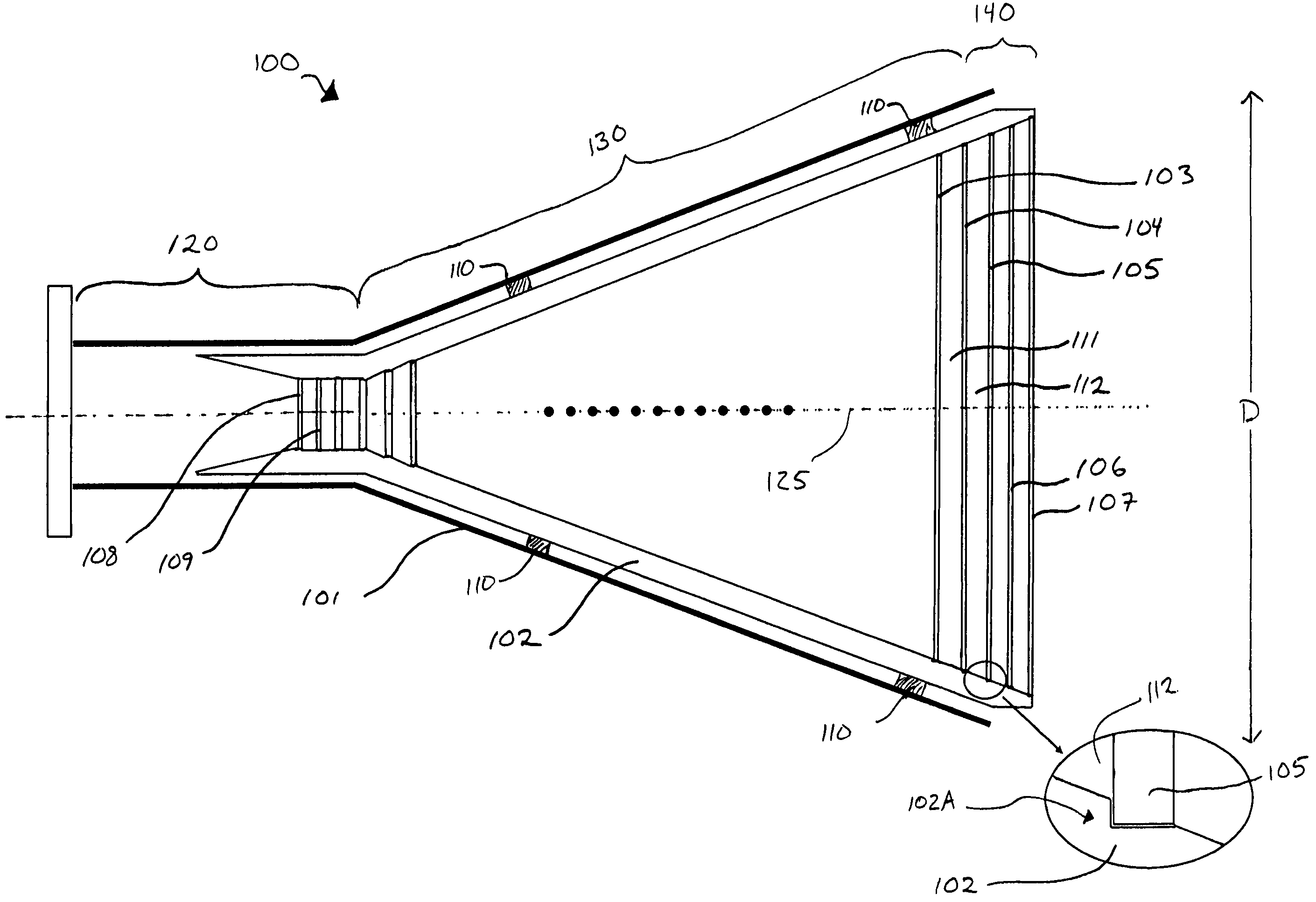
[0023]FIG. 1 shows an axial cut-away view along an axis 125 of a simplified diagram of a horn antenna 100 in accordance with one embodiment of the present invention. Horn antenna 100 includes a conducting horn 101, which has an aperture 140, a tapering region 130, and a throat 120. Conducting horn 101 extends from throat 120 to define aperture 140 having a diameter D. While referred to as a “diameter,” it will be appreciated by those skilled in the art that horn antenna 100 may have a variety of shapes, and that aperture 140 may be circular, elliptical, rectangular, square,...


PUM


Abstract

An artificial dielectric antenna structure for reducing the mass and insertion loss of an antenna is provided. The artificial dielectric antenna structure includes a plurality of layers of dielectric material. Each layer of dielectric material has a dielectric constant. The artificial dielectric antenna structure further includes a plurality of spacing layers interposed between the plurality of layers of dielectric material. Each of the plurality of spacing layers has a dielectric constant lower than the dielectric constant of any of the plurality of layers of dielectric material. The artificial dielectric antenna structure may be disposed within a horn antenna. The artificial dielectric antenna structure may alternately be disposed upon a transmission medium to form a dielectric resonator antenna.

Description

CROSS-REFERENCE TO RELATED APPLICATIONS[0001]The present application claims the benefit of priority under 35 U.S.C. § 119 from U.S. Provisional Patent Application Ser. No. 60 / 626,865 entitled “DUAL-BAND HIGH GAIN DIELECTRIC-LOADED HORN ANTENNA,” filed on Nov. 12, 2004, the disclosure of which is hereby incorporated by reference in its entirety for all purposes.STATEMENT REGARDING FEDERALLY SPONSORED RESEARCH OR DEVELOPMENT[0002]Not applicable.FIELD OF THE INVENTION[0003]The present invention generally relates to antenna systems and, in particular, relates to dielectric-loaded antenna systems.BACKGROUND OF THE INVENTION[0004]Dielectric loading is used to improve the radiation performance and frequency bandwidth of an antenna. However, several drawbacks offset the advantages of dielectric loading. First, dielectric loading can cause increased insertion loss, degrading the strength of a signal. Second, dielectric loading increases the mass of an antenna system, which is particularly tr...

Claims


Application Information

Patent Timeline
IPC IPC(8): H01Q13/00
CPCH01Q13/00H01Q19/08
Inventor LIER, ERIK
Owner LOCKHEED MARTIN CORP
Why Eureka
Try Eureka