Hermetic compressor and freezing air-conditioning system

a compressor and compressor technology, applied in the direction of combustion air/fuel air treatment, positive displacement liquid engine, piston pump, etc., can solve the problems of pressure pulsation, insufficient silencing effect, above-described conventional construction, etc., and achieve the effect of reducing a cost of manufacture and simple shap

Inactive Publication Date: 2008-06-03
PANASONIC APPLIANCES REFRIGERATION DEVICES SINGAPORE
View PDF11 Cites 9 Cited by
  • Summary
  • Abstract
  • Description
  • Claims
  • Application Information

AI Technical Summary

Benefits of technology

[0014]The present invention is to provide an inexpensive low-noise hermetic compressor in which a muffler cover is made into a simple shape only with a single wall surface, thereby decreasing a cost for manufacture, and further, since deformation can be reduced thereby, a sufficiently close contact can be obtained in the connection between a muffler main body and the muffler cover.
[0015]Furthermore, in the above-described conventional constructions, it is an effective measure for obtaining a high efficiency to dispose close to each other the opening portion on the muffler space 14 side of the inlet pipe 15 and the opening portion on the muffler space 14 side of the outlet pipe 16, or the opening portion on the muffler space 32 side of the inlet portion 33 and the opening portion on the muffler space 32 side of the outlet pipe 34 to decrease the fluid resistance. However, the above-described conventional constructions have a disadvantage that a sufficient silencing effect can not be obtained because the fluid resistance is reduced also in relation to pressure pulsations having occurred in the compression chamber 5 and the compression chamber 22.
[0016]Another object of the present invention is to provide low-noise hermetic compressors in which fluid resistance means is added between the opening on the muffler space side of the inlet pipe and the opening portion on the muffler space side of the outlet pipe, thereby attenuating a pressure pulsation having occurred in the compression chamber.

Problems solved by technology

However, the above-described conventional constructions have a disadvantage that a sufficient silencing effect can not be obtained because the fluid resistance is reduced also in relation to pressure pulsations having occurred in the compression chamber 5 and the compression chamber 22.
Besides, the above-described conventional constructions have a disadvantage that pressure pulsations having occurred in the compression chamber 5 and the compression chamber 22 are released as sound sources through the opening portion on the hermetic vessel 1 or 18 side of the inlet pipe 15 or the inlet portion 33, besides they vibrate the wall surfaces of the suction muffler 12 and the suction muffler 27 to make new noise sources.

Method used


Image

  • Hermetic compressor and freezing air-conditioning system
  • Hermetic compressor and freezing air-conditioning system
  • Hermetic compressor and freezing air-conditioning system

Examples


embodiment 1

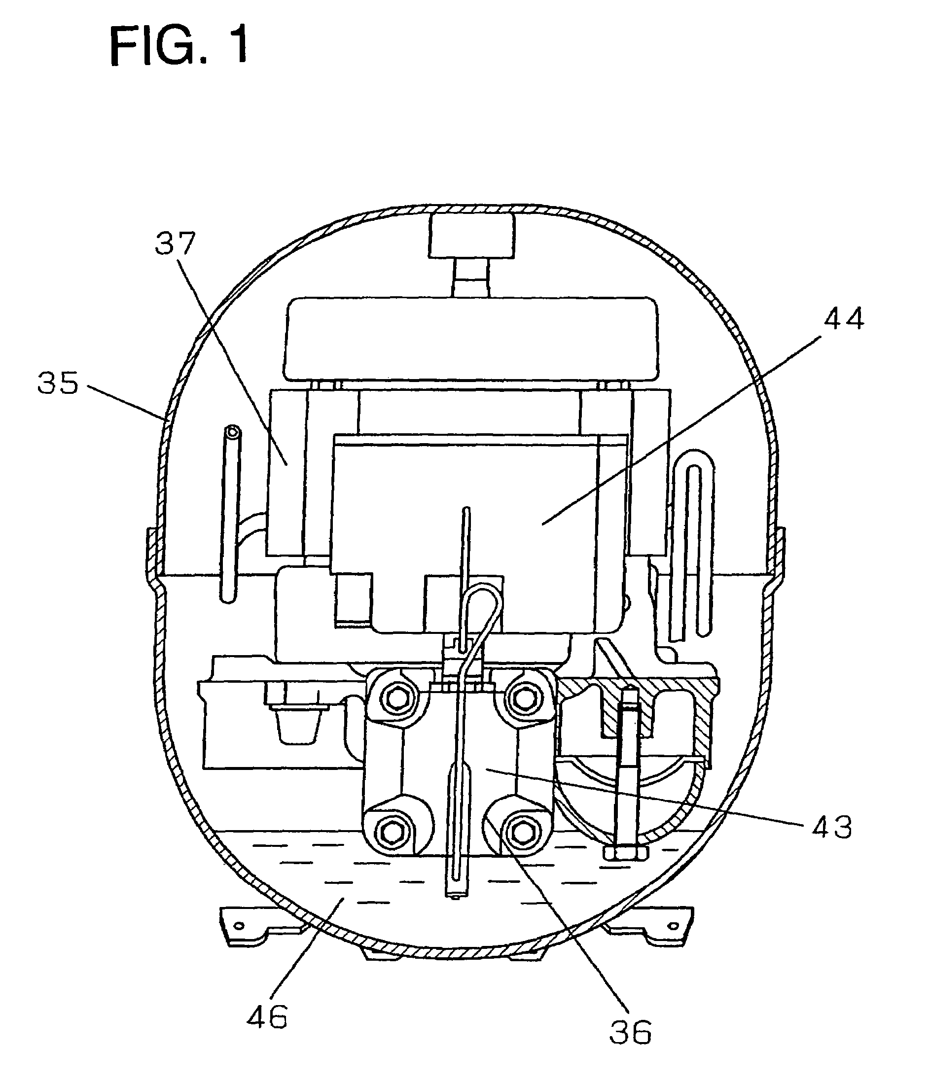
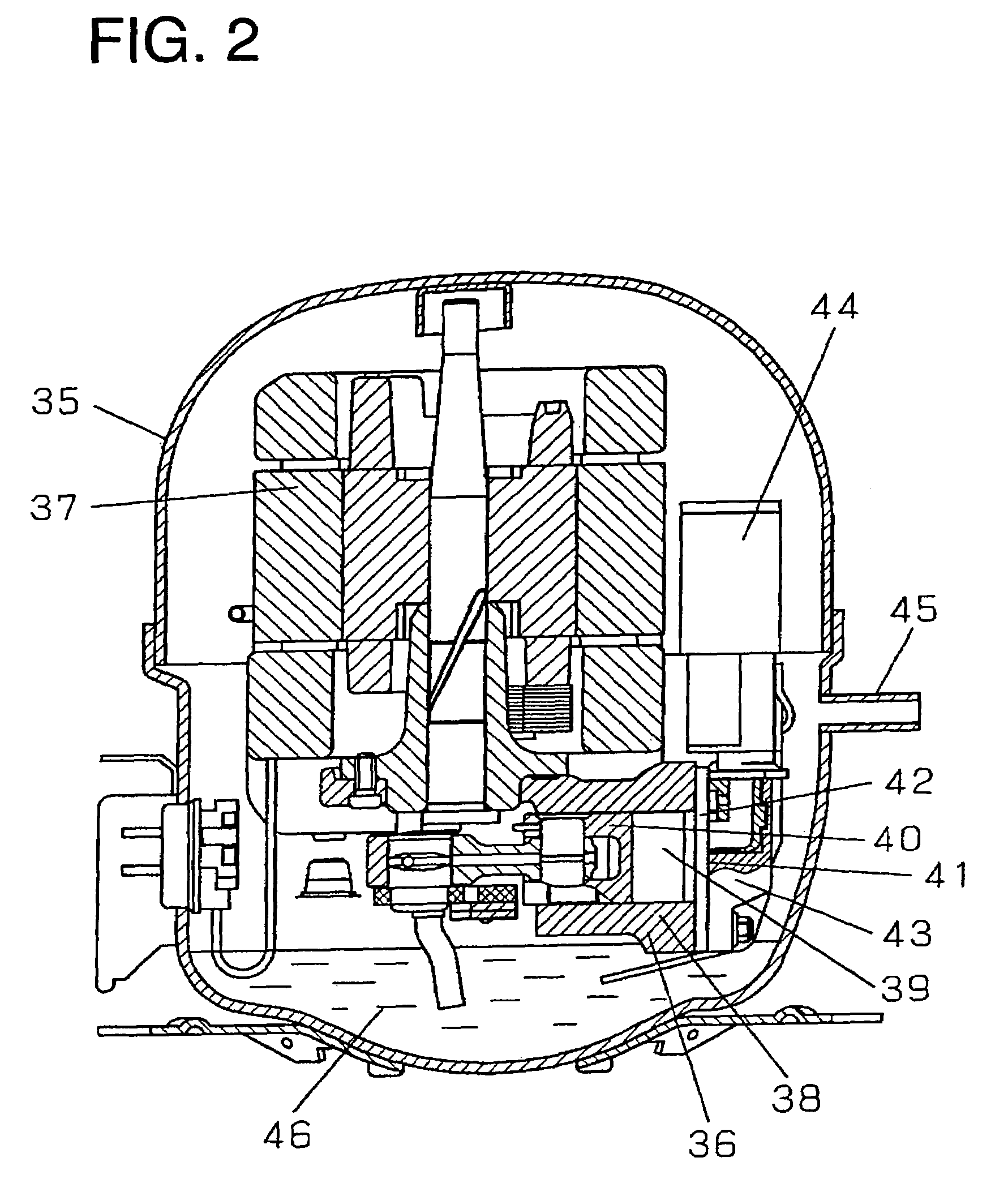
[0062]FIG. 1 is a front view of a principal part of a hermetic compressor according to embodiment 1 of the present invention. FIG. 2 is a sectional view of the principal part of the hermetic compressor according to embodiment 1 of the present invention. FIG. 3 is a sectional view of a principal part of a suction muffler used in the hermetic compressor according to embodiment 1 of the present invention.

[0063]In FIGS. 1, 2, and 3, reference numeral 35 denotes a hermetic vessel. Reference numeral 36 denotes a compressing element, which is accommodated in the hermetic vessel 35. Reference numeral 37 denotes an electric motor element, which is connected with the compressing element 36. Reference numeral 38 denotes a cylinder, which defines a compression chamber 39 of the compressing element 36. Reference numeral 40 denotes a piston, which reciprocates in the cylinder 38. Reference numeral 41 denotes a valve plate, which seals one end of the cylinder 38. Reference numeral 42 denotes a suc...

embodiment 2

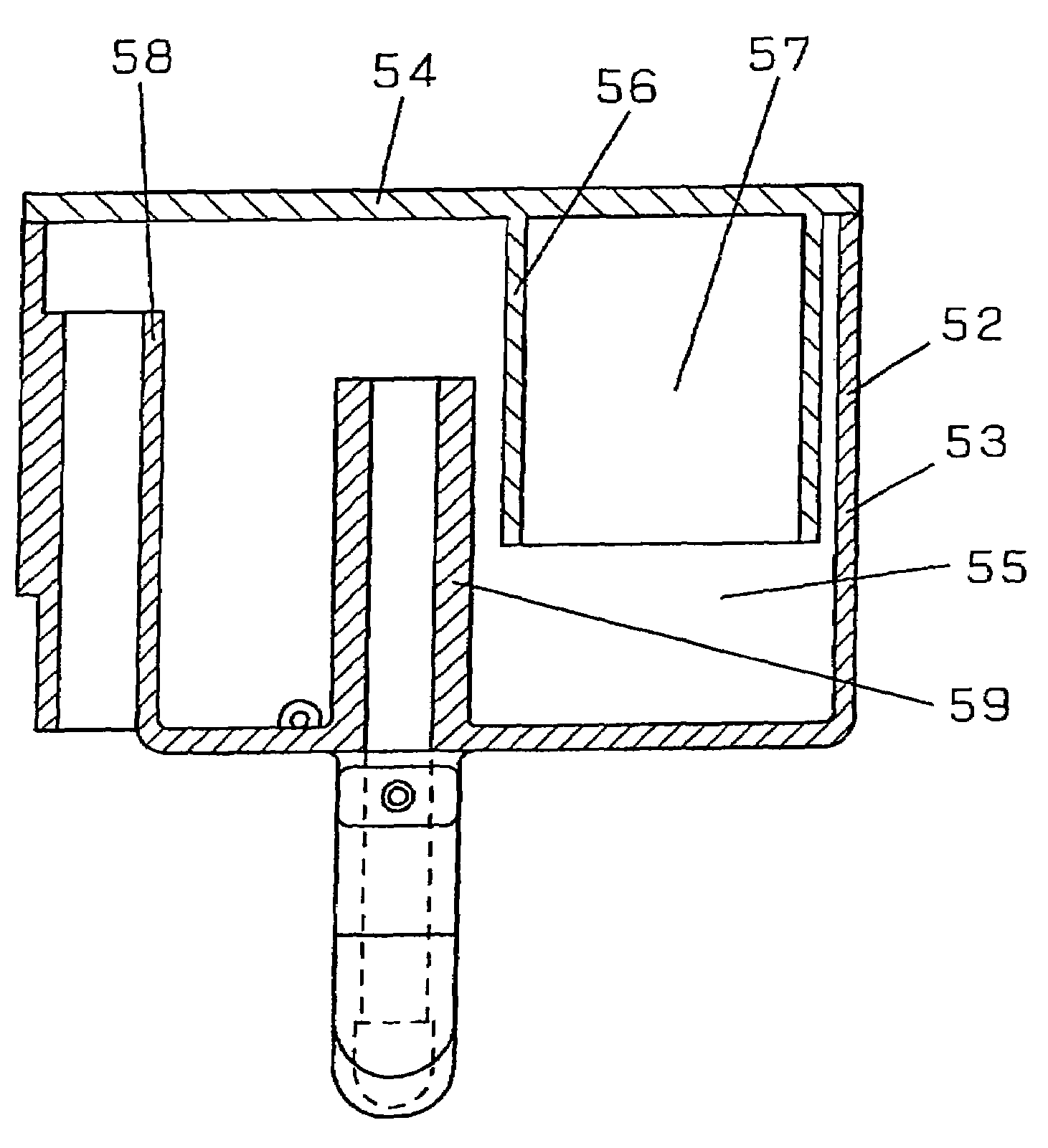
[0069]FIG. 4 is a sectional view of a principal part of a suction muffler used in a hermetic compressor according to embodiment 2 of the present invention and FIG. 5 is a top view of its muffler cover. Note that the hermetic compressor using the suction muffler illustrated in FIG. 4 differs from the hermetic compressor illustrated in FIG. 1 only in the suction muffler, so it is not illustrated.

[0070]In FIGS. 4 and 5, reference numeral 52 denotes a suction muffler, which is made up from a muffler main body 53 and a muffler cover 54. The muffler main body 53 and the muffler cover 54 are joined with each other through a process of welding or the like to form a muffler space 55.

[0071]Reference numeral 56 denotes a cylindrical resonance space wall, which is formed integrally with the muffler cover 54 so as to extend along the inner wall surface of the muffler main body 53 and which defines a resonance space 57. Reference numeral 58 denotes an inlet pipe, whose one end is open in the herm...

embodiment 3

[0073]FIG. 6 is a sectional view of a principal part of a suction muffler used in a hermetic compressor according to embodiment 3 of the present invention. Note that the hermetic compressor using the suction muffler illustrated in FIG. 6 differs from the hermetic compressor illustrated in FIG. 1 only in the suction muffler, so it is not illustrated.

[0074]In FIG. 6, reference numeral 60 denotes a suction muffler, which is made up from a muffler main body 61 and a muffler cover 62. The muffler main body 61 and the muffler cover 62 are joined with each other through a process of welding or the like to form a muffler space 63. Reference numeral 64 denotes a shielding wall, which is formed integrally with the muffler cover 62 on the upper end portion side of the shielding wall 64. The lower end portion of the shielding wall 64 is on the upper end portion side of the shielding wall 64 than a straight line connecting between the center of the opening portion on the suction muffler 60 side ...


PUM


Abstract

In a hermetic compressor in a freezing refrigerating system or an air-conditioning system such as a refrigerator or a showcase, a construction is disclosed for intending to provide a low-noise hermetic compressor by effectively attenuating a pressure pulsation having occurred in a compression chamber with a suction muffler. By this construction, since a muffler cover 20 has a planar simple shape, the deformation upon molding becomes little and it can come into fully close contact with a muffler main body 19. Therefore, the pressure pulsation hardly leaks through the connecting portion between the muffler main body 19 and the muffler cover 20. The full silencing effect that the suction muffler 18 has is obtained and thereby noise can be reduced more effectively.

Description

TECHNICAL FIELD[0001]The present invention relates to a hermetic compressor in a freezing air-conditioning system such as a refrigerator or a showcase.BACKGROUND ART[0002]In recent years, for a hermetic compressor in a freezing refrigerating system or air-conditioning system such as a refrigerator or a showcase, there are required an improvement in efficiency, a reduction of noise and highly reliable techniques, and besides, it is also an important factor to inexpensively provide the compressor.[0003]A conventional hermetic compressor is shown in U.S. Pat. No. 5,971,720.[0004]The above conventional hermetic compressor will be described below with reference to drawings. FIG. 14 is a sectional view of the conventional hermetic compressor. FIG. 15 is an exploded perspective view of a suction muffler attached to a cylinder head of the conventional hermetic compressor.[0005]In FIG. 14, reference numeral 1 denotes a hermetic vessel. Reference numeral 2 denotes a compressing element, which...

Claims


Application Information

Patent Timeline
Patent Type & Authority Patents(United States)
IPC IPC(8): F04B39/00F01N1/02F02M35/00
CPCF04B39/0055F04C29/06
Inventor OSAKA, MASAHIKONISHIHARA, HIDETOSHIOTA, TOSHIHIKOKUBOTA, AKIHIKOMOTEGI, MANABUAWASHIMA, HIROKIKOJIMA, TAKESHINOGUCHI, KAZUHITOKITA, ICHIROKAKUTANI, MASAHIRO
Owner PANASONIC APPLIANCES REFRIGERATION DEVICES SINGAPORE
Why Eureka
Try Eureka