Coaxial cable-connector termination

a technology of coaxial cable and connector, which is applied in the direction of connections, basic electric elements, electric devices, etc., can solve the problems of time-consuming operation, inconvenient removal of metallic foil in this way, and the need for special tools, so as to eliminate any clearance space, eliminate longitudinal electric fields, and good electrical performance

Inactive Publication Date: 2008-06-03
ITT MFG ENTERPRISES LLC
View PDF4 Cites 303 Cited by
  • Summary
  • Abstract
  • Description
  • Claims
  • Application Information

AI Technical Summary

Benefits of technology

[0007]In use, the cable center conductor, the cable insulator surrounding the center conductor and the cable conductive foil, are received into the bore in the rear end of the coaxial connector. The conductive braid is placed around the rear end portion of the connector outer connector. The cable portion with foil on the outside is easily received into a rear part of the bore in the connector outer conductor, but the reduced diameter of a front bore part provides an interference fit between the conductive foil of the cable and the inner surface of walls of the bore in the connector outer conductor. This interference fit eliminates any clearance space between the conductive foil of the cable and the inner surface of the bore, and thereby eliminates a longitudinal electric field between the conductive foil and the connector body.
[0008]It has been found that prevention of such a longitudinal electric field is an effective way of maintaining the radial orientation of the electric field, thereby ensuring good electrical performance at higher frequencies.

Problems solved by technology

The removal of the metallic foil in this way is an inconvenience for cable assembly manufacturers and cable installers because it requires the foil to be stripped back behind (within) the braid that surrounds it.
This operation is time consuming and requires special tools, and may lead to damage of the braid.
However, this presents a problem in terms of electrical performance.
However, at higher frequencies, a convoluted signal path occurs, and a higher than expected return loss or VSWR (voltage standing wave ratio) is exhibited.

Method used


Image

  • Coaxial cable-connector termination
  • Coaxial cable-connector termination
  • Coaxial cable-connector termination

Examples


Embodiment Construction

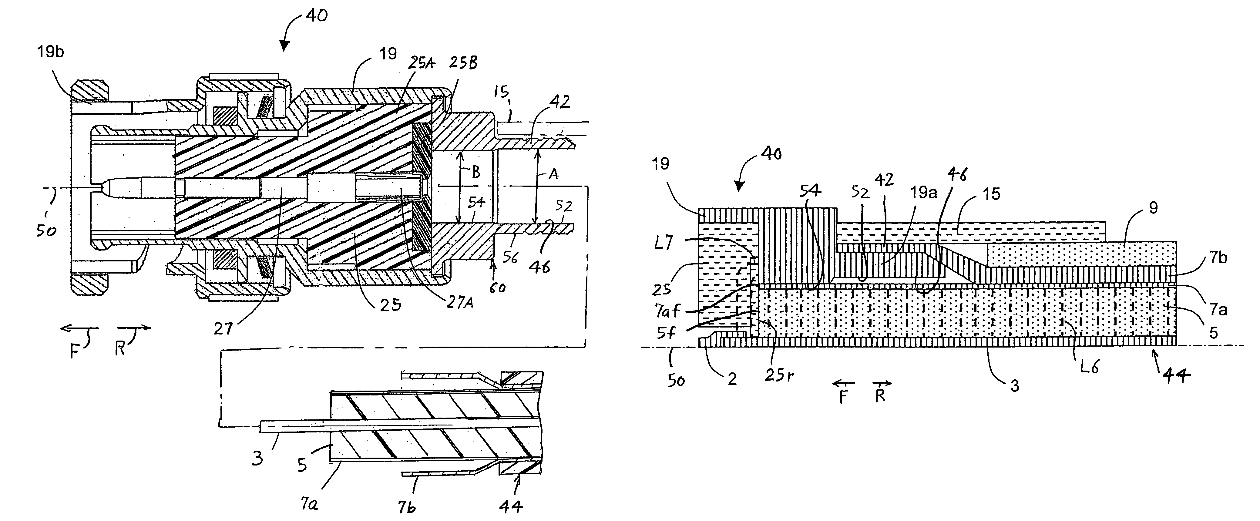
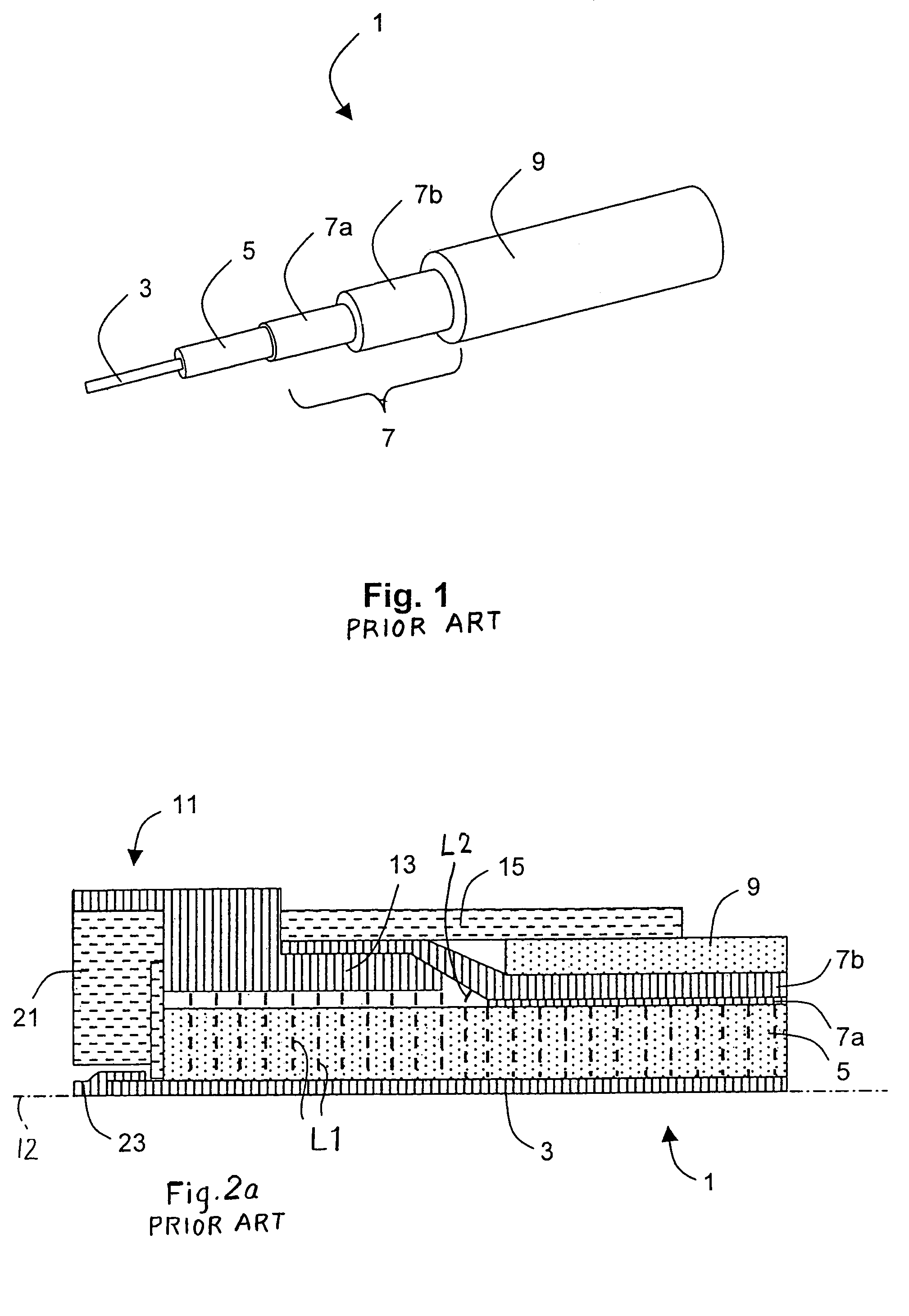
[0017]FIG. 1 shows a prior art high performance (low losses at frequencies of about 1 GHz and somewhat higher) coaxial cable 1. The cable includes coaxial inner and outer cable conductors 3, 7, a dielectric layer or insulator 5 between the conductors, and a protective outer jacket 9. The cable outer conductor 7 includes a conductive foil 7a lying around and against the insulator 5 and a conductive braid 7b lying around the foil.

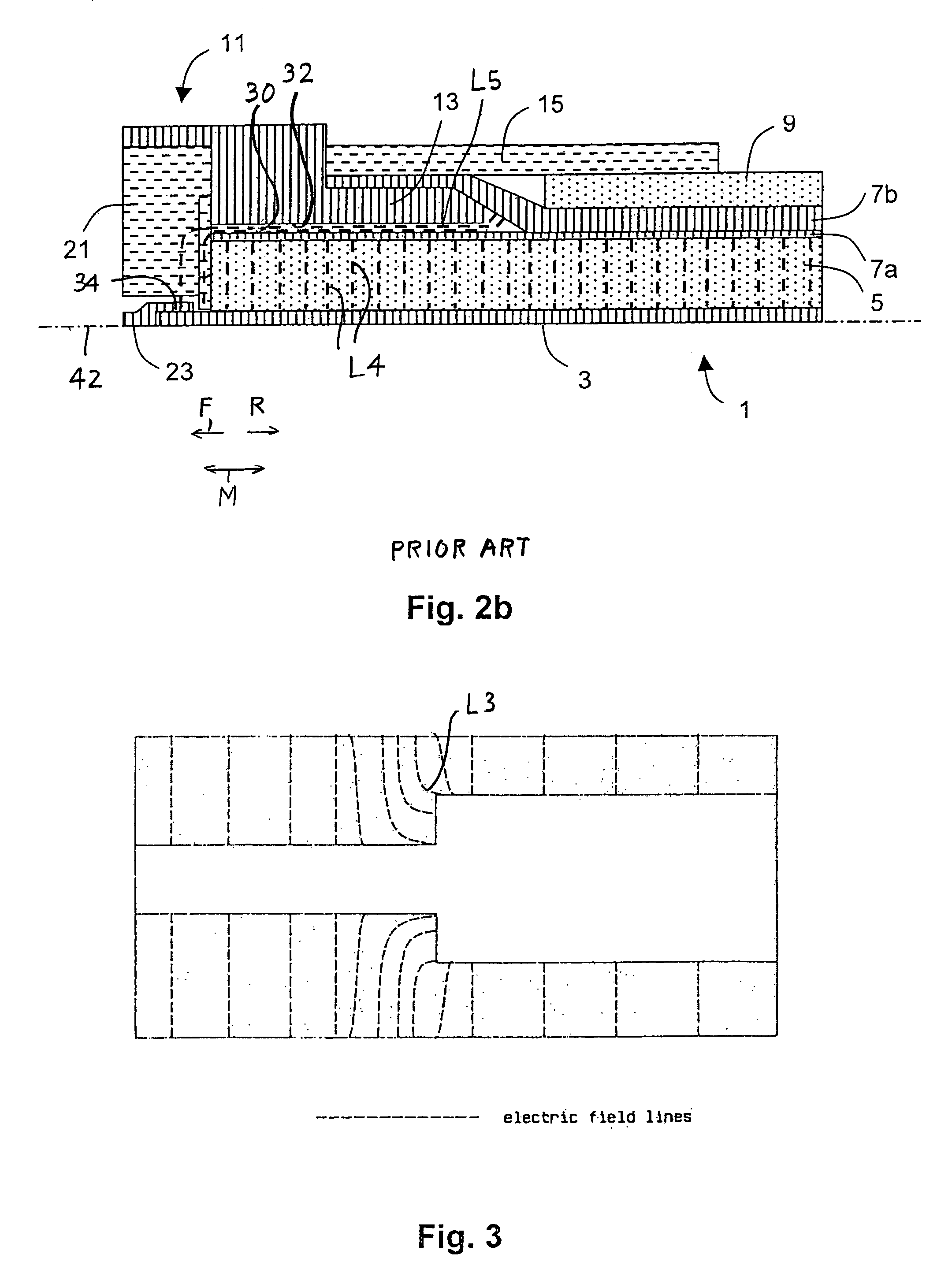
[0018]FIG. 2a shows the coaxial cable 1 of FIG. 1 terminated to a prior art coaxial connector 11. Only the right portion of the connector 11 that receives the cable 1 is shown in the Figure, and only portions on one side of the coincident cable and connector axis 12 is shown. The cable jacket 9, has been stripped back (cut away) from around the cable center conductor 3 and the insulator 5. The conductive foil 7a also has been stripped back to a location within the cable braid 7b to be approximately flush with the cable jacket 9. The center conductor 3 and the...


PUM


Abstract

A high frequency coaxial cable having a foil (7a) between the cable insulator (5) and cable braid (7b), is terminated to a coaxial connector (40) in a manner that allows fast and easy cable preparation and results in a termination with minimal axial electric field lines that cause a high insertion loss and a high VSWR (voltage standing wave ratio). A bore (46) at the rear portion of the connector outer conductor, receives the cable insulator with foil around the cable insulator. The bore has a front part (54) that forms an interference fit around the foil, to avoid an axially-extending gap which might contain axially-extending field lines. The front of cable insulator and foil are flush and both abut the insulation (25) of the connector.

Description

CROSS-REFERENCE[0001]Applicant claims priority from British patent application 0419303.3 filed 31 Aug. 2004.BACKGROUND OF THE INVENTION[0002]This invention relates to a coaxial connector for terminating to a high performance coaxial cable of the type that has a wrapped conductive shield. A coaxial cable includes a solid or stranded inner cable conductor surrounded by a layer of polymer dielectric material. The dielectric material is precisely centered within a woven braid outer cable conductor, and the cable has an outer jacket of polymer material. The outer cable conductor defines a ground return path which is necessary for microwave signal transmission.[0003]High performance, low loss coaxial cables have been developed to transmit higher frequencies with minimal impedance discontinuities. With low loss dielectrics, these cables may transmit higher power levels with minimal attenuation. The high performance cables generally comprise an inner cable conductor surrounded by a low loss...

Claims


Application Information

Patent Timeline
Patent Type & Authority Patents(United States)
IPC IPC(8): H01R9/05
CPCH01R9/0524H01R13/646
Inventor HOSLER, SR., ROBERT CRAIG
Owner ITT MFG ENTERPRISES LLC
Why Eureka
Try Eureka