Light source unit and image display unit

a technology of light source and image display unit, which is applied in the direction of instruments, lighting and heating equipment, transportation and packaging, etc., can solve the problems of difficult to provide laser lights at substantially the same spaces and difficult to apply laser lights to exact positions

Inactive Publication Date: 2008-06-10
SEIKO EPSON CORP
View PDF14 Cites 13 Cited by
  • Summary
  • Abstract
  • Description
  • Claims
  • Application Information

AI Technical Summary

Benefits of technology

[0009]Since the optical-path changing section that substantially collimates the light beams and reduces the distance among the light beams as compared with the distance of the light beams incident from the light sources is provided, the positions of incidence of the light beams in the region being irradiated can be brought close to one another. The use of the optical-path changing section allows the light beams to be brought close to one another, for example, to substantially the same space as the pitch of pixels regardless of the size of the light sources. This achieves a light source unit capable of applying a plurality of light beams in proximity.
[0010]Preferably, the plurality of light sources provide the substantially parallel light beams to the optical-path changing section; the optical-path changing section has a reflecting plane having steps corresponding to the light sources; and the reflecting plane reflects the light beams from the corresponding light sources. The use of the stepped reflecting plane corresponding to the light sources allows the substantially parallel incident light beams to be output such that the light beams are substantially parallel to one another and the distance among the light beams is smaller than that at entering from the light sources. Thus the plurality of light beams can be applied in proximity.
[0012]Preferably, the optical-path changing section includes a plurality of mirrors that reflect the light beams. Thus a plurality of light beams can be applied in proximity. The optical-path changing section can easily be constructed such that a plurality of mirrors are placed one on another to have steps corresponding to the light sources.
[0015]Preferably, the light source unit further includes a detecting section that detects the light beams. It is preferable that the reflecting plane reflects part of the light beams incident from the light sources and transmits part of the other of the light beams incident from the light sources; the detecting section detects the light beams that has passed through the reflecting plane; and the light sources control the amount of the light beams to be emitted according to the detection result of the detecting section. The light beams reflected by the reflecting plane are applied such that they are substantially in parallel and at a distance smaller than that incident from the light sources. The light beams that have passed through the reflecting plane travel in a different direction from the direction of lighting into a detecting section. The light source unit can feedback-control the light sources by using the light beams that have passed through the reflecting plane. This allows a plurality of light beams to be brought close to one another at a preferable balance of light amount.

Problems solved by technology

This may also make it difficult to apply the laser lights to an exact position according to an image signal.
However, this produces the problem of difficulty in providing the laser lights at substantially the same spaces as the pitch of pixels.

Method used


Image

  • Light source unit and image display unit
  • Light source unit and image display unit
  • Light source unit and image display unit

Examples


first embodiment

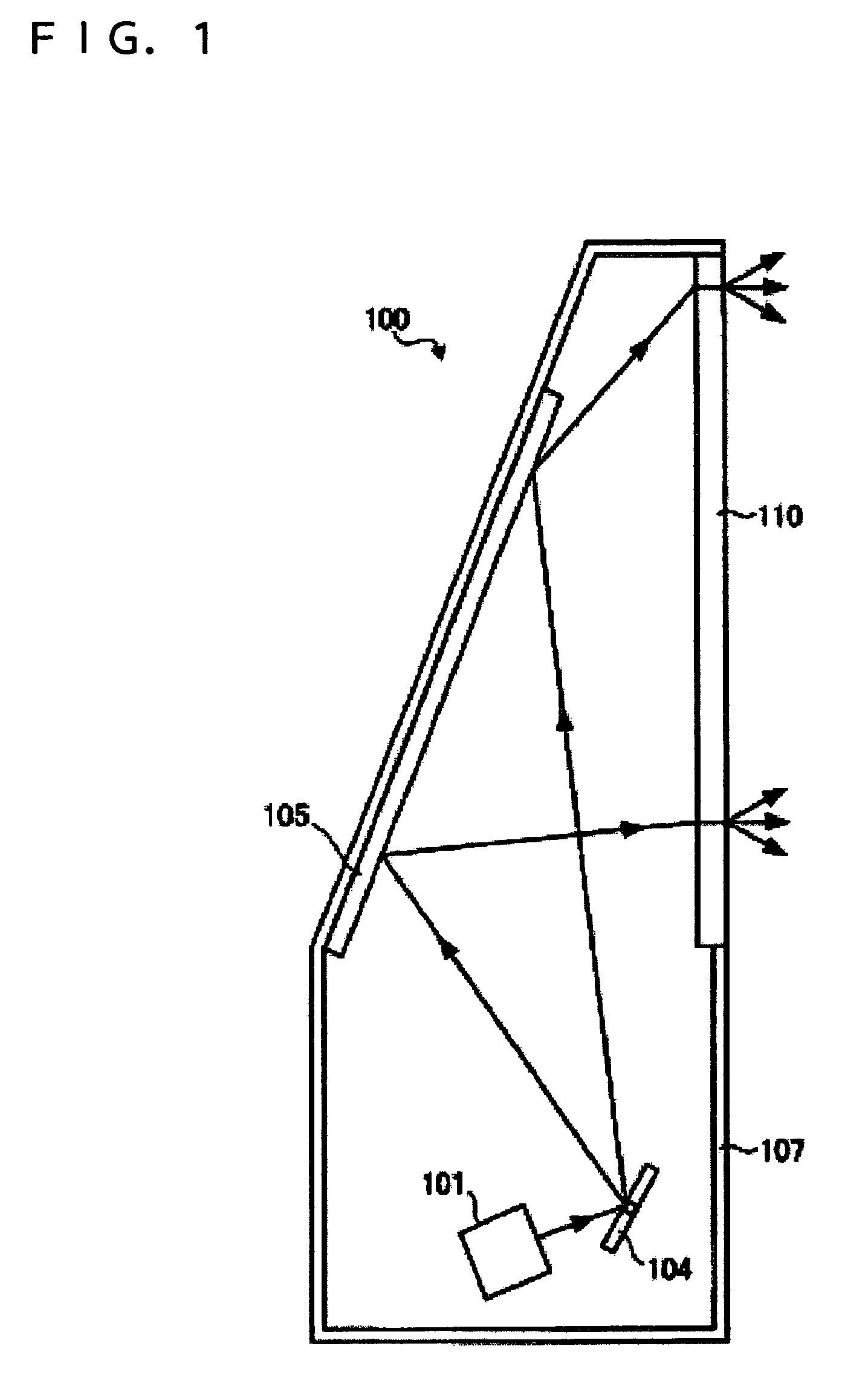
[0026]FIG. 1 is a schematic diagram of an image display unit 100 according to a first embodiment of the invention. The image display unit 100 is a so-called rear projector for displaying images in such a way that laser beam light that is applied onto one surface of a screen 110 and is output from the other surface of the screen 110 is displayed. A light source unit 101 applies laser light responsive to an image signal toward a galvano mirror 104. The galvano mirror 104 reflects the laser light from the light source unit 101 toward a reflecting mirror 105.

[0027]The galvano mirror 104 is a scanning section for applying the light from the light source unit 101. The galvano mirror 104 applies laser light in a two-dimensional direction by rotating around specified two shafts interesting at right angles. The galvano mirror 104 can be manufactured by, for example, micro electro mechanical system (MEMS) technology. The reflecting mirror 105 is provided on the inner surface of a casing 107 a...

second embodiment

[0043]FIG. 5 is a schematic diagram of a light source unit 501 according to a second embodiment of the invention. The same components as those of the light source unit 101 according to the first embodiment are given the same reference numerals and their duplicate description will be omitted. The light source unit 501 includes a convergent lens 511 and a divergent lens 512. The convergent lens 511 and the divergent lens 512 serve as optical-path changing sections for changing the optical paths of the color lights. Substantially parallel color lights are incident on the convergent lens 511. The convergent lens 511 is a convex lens that converges the color lights from the light sources 201, 202, and 203.

[0044]The lights from the convergent lens 511 are incident on the divergent lens 512. The divergent lens 512 is a concave lens that diverges the lights from the convergent lens 511 into substantially parallel lights. Thus the color lights from the light sources 201, 202, and 203 are out...

third embodiment

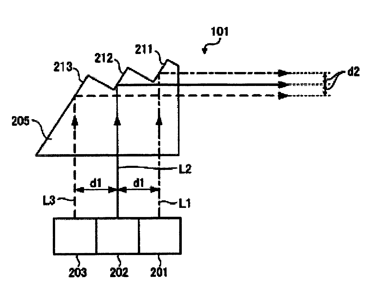
[0046]FIG. 6 is a schematic diagram of a light source unit 601 according to a third embodiment of the invention. The same components as those of the light source unit 101 according to the first embodiment are given the same reference numerals and their duplicate description will be omitted. The light source unit 601 includes a prism element 605 that transmits color lights. The prism element 605 serves as an optical-path changing section for changing the optical paths of the color lights. The prism element 605 can be made of a glass material or a transparent resin material, as is the prism element 205 according to the first embodiment. The prism element 605 can be formed by cutting or injection molding.

[0047]The prism element 605 has a triangular shape. Substantially parallel color lights are incident on the prism element 605. The color lights incident on the prism element 605 are refracted by a light-exiting plane 611. The light-exiting plane 611 serves as a refracting interface tha...


PUM


Abstract

A light source unit includes: a plurality of light sources that provide light beams; and an optical-path changing section that outputs the light beams emitted from the light sources such that the light beams are substantially parallel to one another and the distance therebetween are smaller than the distance at entering from the light sources, thereby changing the optical path of the light beams.

Description

[0001]The present application claims priority to Japanese Patent Application No. 2004-350820 filed Dec. 3, 2004, which is hereby expressly incorporated by reference herein in its entirety.BACKGROUND[0002]1. Technical Field[0003]The present invention relates to a light source unit and an image display unit, and in particular, to a light source unit for displaying an image by using laser light modulated in response to an image signal, and a technique of an image display unit that uses the light source unit.[0004]2. Related Art[0005]Image display units that display images using laser light have been proposed in recent years. The image display units that use laser light include front projectors and rear projectors. Laser light is suitable for bright images with high color-reproducibility owing to its high monochromaticity and directivity. For displaying of color images with laser light, for example, a red laser light (hereinafter, referred to as an R-light), a green laser light (hereina...

Claims


Application Information

Patent Timeline
Patent Type & Authority Patents(United States)
IPC IPC(8): G03B21/26F21V5/00
CPCG02B27/1053G02B27/108G02B27/126G02B27/143G02B27/144G03B21/10G03B21/208G02B26/10
Inventor TAKEDA, TAKASHI
Owner SEIKO EPSON CORP
Why Eureka
Try Eureka