Optical encoder for measuring displacement

a technology of optical encoder and displacement, applied in the field of optical encoder, can solve the problems of large waveform distortion of displacement signals composed of pseudo sine waves, adverse effects of non-uniform illumination distribution on optical encoders, measurement errors of positions, etc., and achieve the effect of reducing the component of high-order harmonic distortion and increasing the measurement precision of optical encoders

Inactive Publication Date: 2008-06-10
CANON KK
View PDF18 Cites 7 Cited by
  • Summary
  • Abstract
  • Description
  • Claims
  • Application Information

AI Technical Summary

Benefits of technology

[0049](c) On the basis of the definitions according to (b), a measurement precision of an optical encoder is increased by reducing the high-order harmonic distortion component of a displacement signal by controlling the aperture ratio AR of the square wave amplitude grating at an appropriate gap position z.

Problems solved by technology

The displacement signal composed of such a pseudo sine wave signal has a large waveform distortion.
When a position is measured using such a displacement signal having such a variation in distortion-ratio, a large interpolation error occurs, which results in a measurement error of the position.
In this structure, the optical encoder has an adverse effect from the non-uniform illumination distribution.
Therefore, the reduction in the distortion at any gap is difficult.
The first drawback is that the intensity pattern I(x) expressed as equation (1) represents the intensity transmission ratio distribution of the grating.

Method used


Image

  • Optical encoder for measuring displacement
  • Optical encoder for measuring displacement
  • Optical encoder for measuring displacement

Examples


first exemplary embodiment

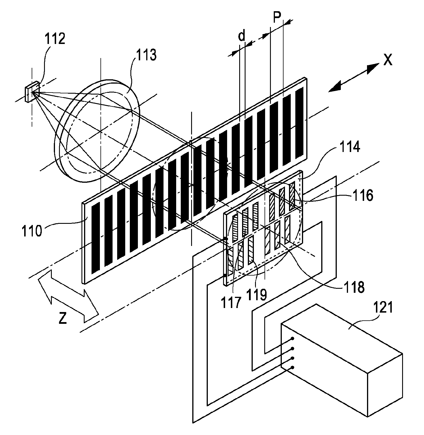
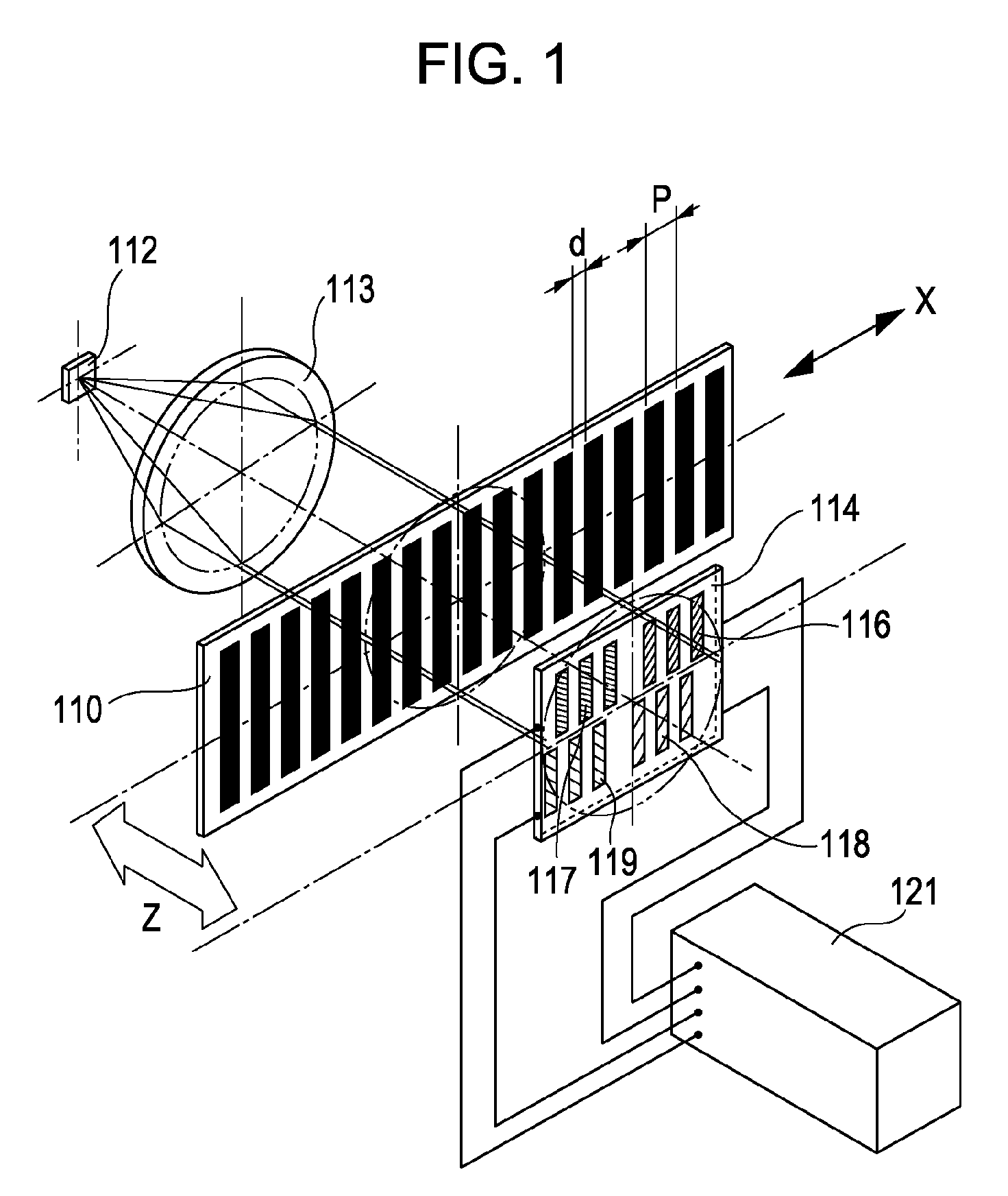
[0078]Exemplary embodiments of the present invention are described below with reference to the accompanying drawings. FIG. 1 is a schematic illustration of the structure of an optical encoder according to a first exemplary embodiment of the present invention.

[0079]A grating is evenly formed on a main scale 110 with a predetermined spacing between the slits thereof. The main scale 110 is secured to a moving object to be measured and moves in the grating arrangement direction indicated by an arrow in FIG. 1 (the x-axis direction).

[0080]Additionally, the main scale 110 receives light from a light source 112 and forms interference fringes on the side remote from the light source 112. In the first exemplary embodiment, the grating formed on the main scale 110 functions as a square wave amplitude grating (a first grating).

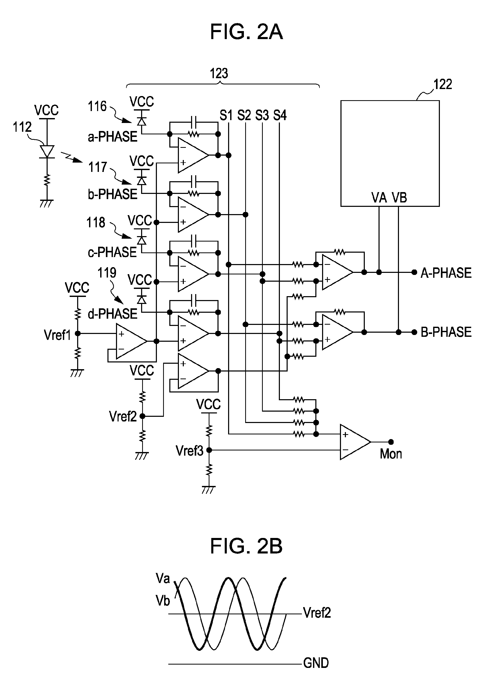
[0081]A light-receiving-element array 114 is secured at a position at which the interference fringes caused by the diffraction of the main scale 110 are formed. On the l...

second exemplary embodiment

[0186]The case where divergent light beams are emitted to the main scale is described next.

[0187]In the first exemplary embodiment, equation (25) is derived in terms of a diffraction image when parallel beams are emitted to the main scale. In a second exemplary embodiment, the case where divergent light beams are emitted to the main scale is discussed.

[0188]FIG. 13 illustrates the structure of a reflective encoder.

[0189]The main scale 110 is illuminated with divergent light beams from the light source 112. The reflected diffracted light from the main scale 110 forms interference fringes on an index scale 120.

[0190]The index scale 120 and the main scale 110 are disposed with a gap Z therebetween. According to this structure, on a surface of the index scale 120, interference fringes having a period twice the period of a pitch P of the main scale 110 are formed. The other structures are similar to those of the first exemplary embodiment. Accordingly, descriptions thereof are not repeat...

third exemplary embodiment

[0225]In the above-described exemplary embodiments, the grating is formed on a plane. In a third exemplary embodiment, the grating is disposed on a curved surface.

[0226]FIGS. 16A-C illustrate the structure of an optical encoder incorporated in an interchangeable lens of a single-lens reflex camera.

[0227]As shown in FIG. 16A, a main scale 110 is bonded to portions 301 of the inner surface of a cam ring 300 using a two sided adhesive tape. The cam ring 300 can be used for moving an auto-focus lens.

[0228]This example of an optical encoder is a rotary encoder in which the rotation angle of the cam ring 300, which is an object to be measured, is measured by use of a detection head 200.

[0229]FIG. 16B is an enlarged view of the main portion of the optical encoder. FIG. 16C illustrates the structure of the detection head 200. The detection head 200 includes a light source 112 and a light-receiving-element array 120 that optically operates in the same manner as an index scale. Here, Z denote...


PUM


Abstract

At least one exemplary embodiment is directed to an optical encoder which includes a first diffraction grating having a desired optical effective aperture ratio at an appropriate gap position so as to eliminate and / or reduce high-harmonic components from the light intensity distribution of interference fringes and reduce high-order spatial frequency components overlapped on a displacement signal of the interference fringes formed by the first diffraction grating.

Description

BACKGROUND OF THE INVENTION[0001]1. Field of the Invention[0002]The present invention relates to an optical encoder configured to measure the displacement of a diffraction grating, more particularly though not exclusively, measuring the displacement by emitting a light beam from a light source onto the diffraction grating and counting light-dark fringes in the interference pattern formed.[0003]2. Description of the Related Art[0004]Known optical encoders include a main scale formed from a square wave amplitude grating in which light transmissive portions and light shielding portions (or light reflective portions and light non-reflective portions) having the same width are arranged at a predetermined pitch.[0005]A transmissive optical encoder emits parallel light beams to the scale. The light beams passing through the scale and having a square wave pattern further pass through an index scale in which light transmissive portions and light shielding portions are arranged at a predeterm...

Claims


Application Information

Patent Timeline
Patent Type & Authority Patents(United States)
IPC IPC(8): G01D5/34
CPCG01D5/38
Inventor IGAKI, MASAHIKOATSUTA, AKIO
Owner CANON KK
Why Eureka
Try Eureka