Total internal reflection fluorescence microscope

a fluorescence microscope and internal reflection technology, applied in the field of total internal reflection fluorescence microscope, can solve the problems of difficult to increase the effective diameter of the objective lens, considerable space is needed, and the operation properties are remarkably impaired

Inactive Publication Date: 2008-06-10
OLYMPUS CORP
View PDF7 Cites 9 Cited by
  • Summary
  • Abstract
  • Description
  • Claims
  • Application Information

AI Technical Summary

Benefits of technology

[0050]FIG. 17A is a diagram showing a function of a conventional TIRFM;
[0051]FIG. 17B is a diagram showing the function of the conventional TIRFM;
[0052]FIG. 17C is a diagram showing the function of the conventional TIRFM;
[0053]FIG. 18 is a constitution diagram of the conventional TIRFM; and
[0054]FIG. 19 is a constitution diagram of the conventional TIRFM.

Problems solved by technology

However, it is difficult to increase the effective diameter of the objective lens 1 while keeping a standard diameter of an attaching screw of the objective lens 1.
Therefore, a considerable space is necessary including a holding section of a rotary mechanism and a space of a track of the rotating laser illuminating device 7.
It is supposed that operation properties are remarkably impaired.
Therefore, the laser beam with which another part is irradiated is useless.
Therefore, there is a principle problem that a range to be observed differs, when the wavelength differs even at the equal laser beam incidence angle.
There is also a realistic problem that a depth position of a tissue in a cell corresponding to each wavelength differs.
However, in cases where a simultaneous property in a strict meaning is required such as a case where a fast phenomenon is traced, there is a restriction on a high-speed switch.
The dichroic mirror of the multi-band has a high difficulty in manufacturing, and is expensive.
Furthermore, the dichroic mirror of the multi band has a bad separation level of the wavelength, and brightness and SN ratio of a fluorescent image are deteriorated.
Therefore, a capability of the objective lens 1 is deteriorated.
Therefore, a considerable space is required including the space of the track of the holding section of the rotation mechanism or the rotating laser illuminating device 7.
Moreover, each TIRFM has a common problem.

Method used


Image

  • Total internal reflection fluorescence microscope
  • Total internal reflection fluorescence microscope
  • Total internal reflection fluorescence microscope

Examples


first embodiment

[0055]the present invention will be described hereinafter with reference to the drawings.

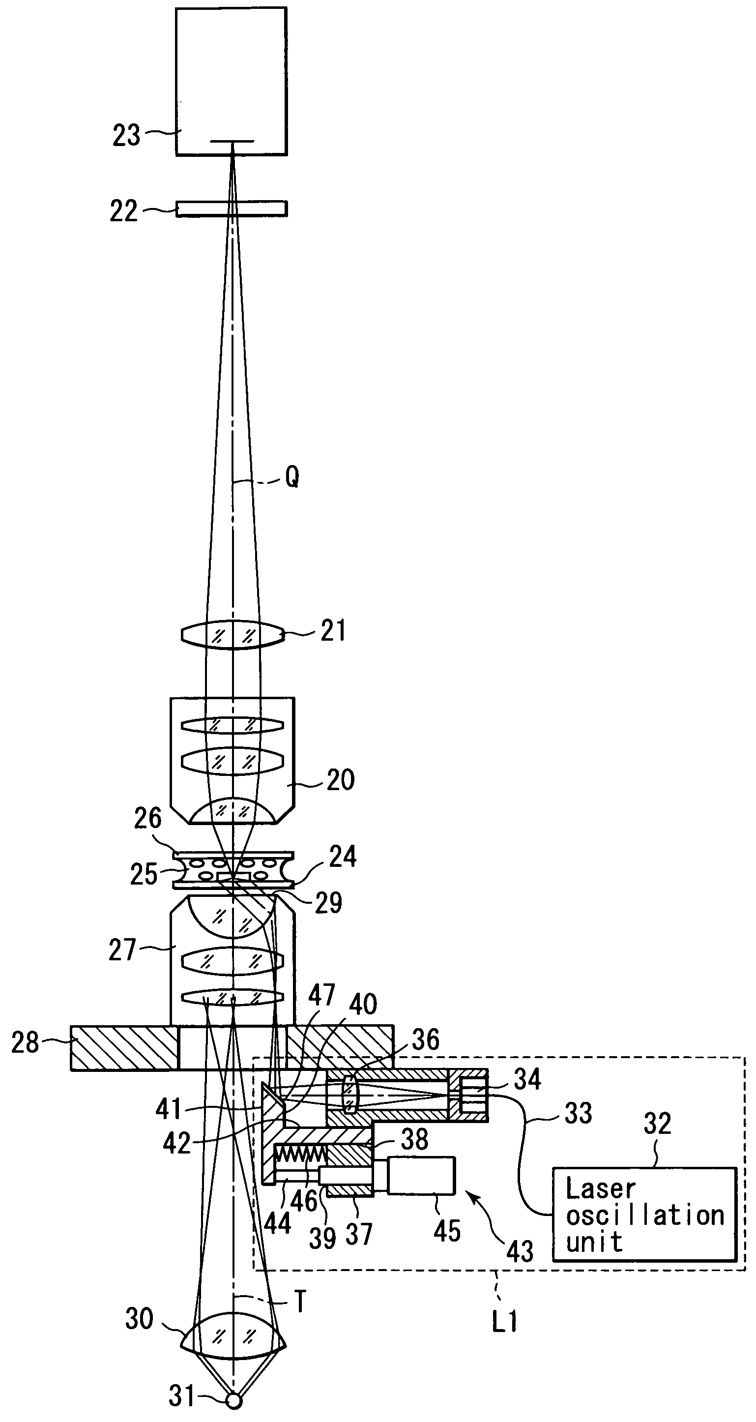
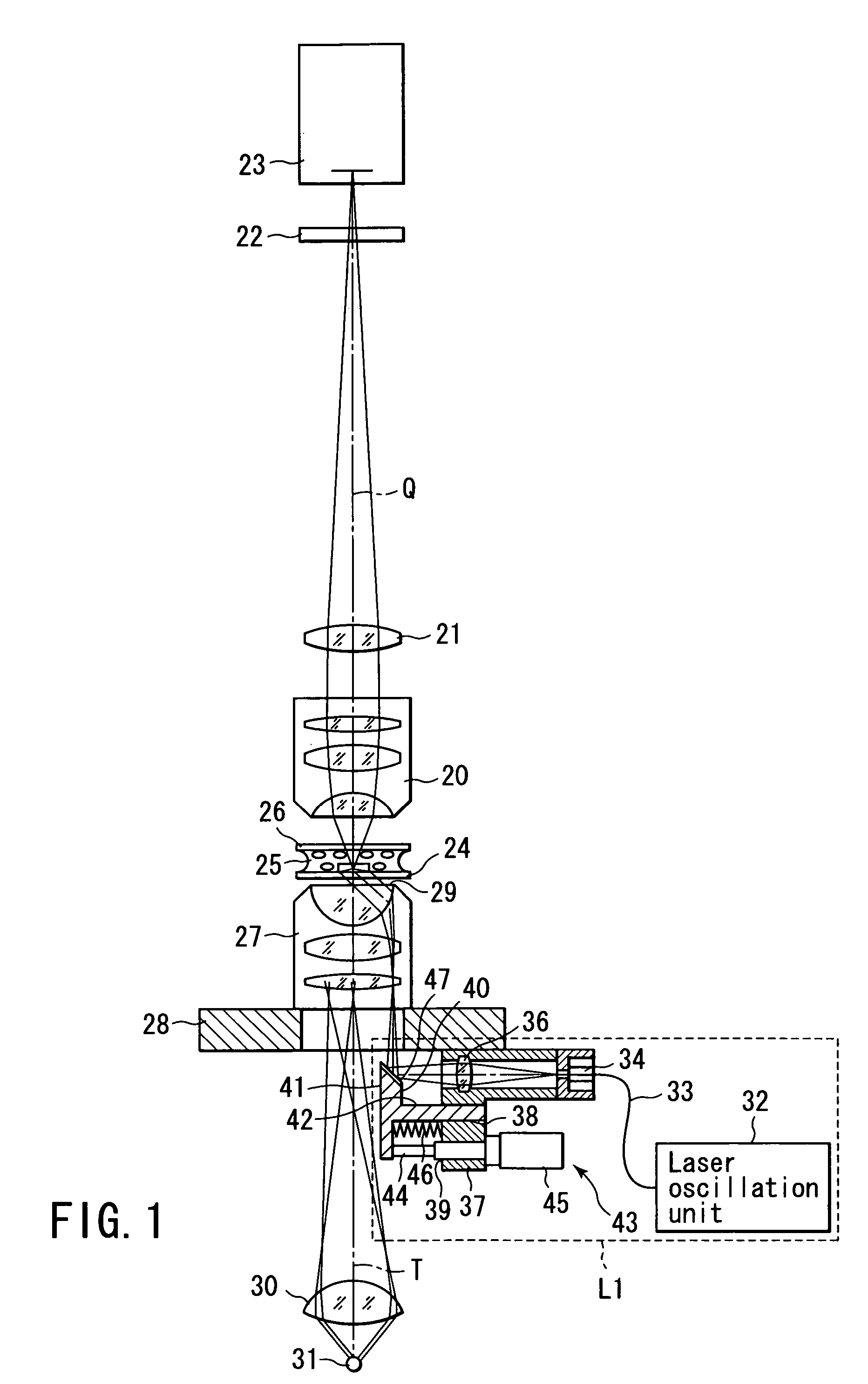
[0056]FIG. 1 is a constitution diagram of an erected type total internal reflection fluorescence microscopy (TIRFM). An image forming lens 21, emission filter 22, and image pick-up device 23 are disposed on an observation optical path Q of an objective lens 20. The emission filter 22 is a band pass filter which passes a light only of a specific wavelength band λE1 longer than a wavelength λL1 of a laser beam output from a laser oscillation unit 32 described later. The image pick-up device 23 is disposed in a focal position of the image forming lens 21.

[0057]A slide glass for observation 24 is disposed under the objective lens 20. A specimen 25 is placed on the slide glass 24. The specimen 25 is covered with a cover glass 26.

[0058]A condenser lens 27 is disposed in a position facing the objective lens 20 via the slide glass 24. The condenser lens 27 is disposed on a base 28. An immersion oil 29 i...

second embodiment

[0090]the present invention will be described with reference to the drawings. It is to be noted that the same part as that of FIG. 1 is denoted with the same reference numerals and detailed description thereof is omitted.

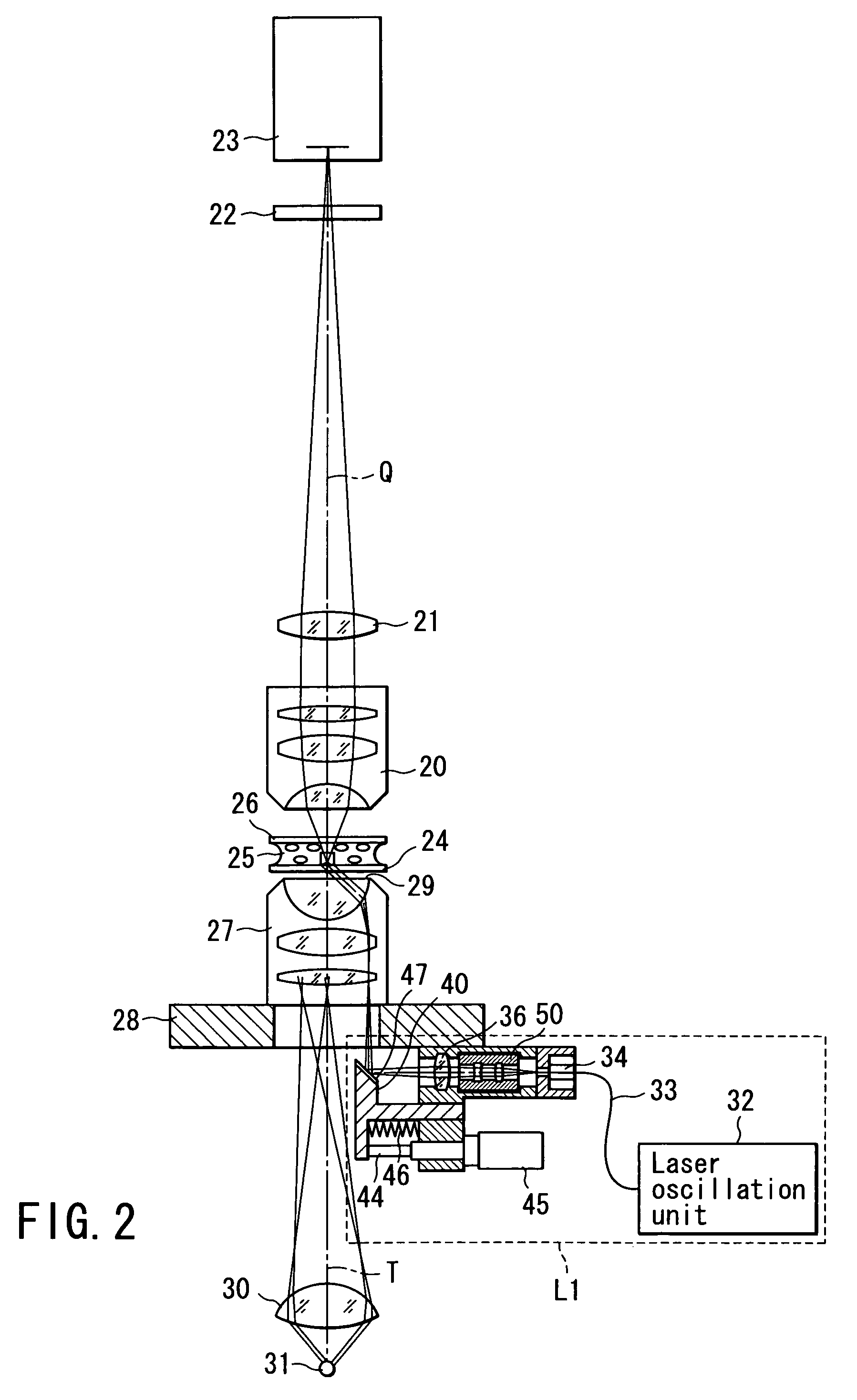
[0091]FIG. 2 is a constitution diagram showing the erected type total internal reflection fluorescence microscopy (TIRFM). A conversion lens unit 50 is disposed between the fiber emission end 34 and the condensing lens 36. The conversion lens unit 50 is integrally detachably inserted with respect to a laser introductory optical path between the fiber emission end 34 and the condensing lens 36.

[0092]FIGS. 3 and 4 are enlarged top plan views of the conversion lens unit 50. A shelter space portion 51 is disposed in the side surface of the support section 35 including a hollow structure. The conversion lens unit 50 is provided with a knob 52. The knob 52 protrudes out of the shelter space portion 51 through the wall of the shelter space portion 51. The conversion lens u...

third embodiment

[0105]the present invention will be described with reference to the drawing. It is to be noted that the same part as that of FIG. 2 is denoted with the same reference numerals, and detailed description is omitted.

[0106]FIG. 5 is a constitution diagram of the erected type total internal reflection fluorescence microscopy (TIRFM). An objective lens for high-magnification observation 61 and an objective lens for low-magnification observation 62 are attached to an objective lens switching section 60.

[0107]FIG. 6 is a diagram showing a switch mechanism for the respective objective lenses 61, 62. A member for switching 63, such as a rack, is disposed on the side surface of the objective lens switching section60. The member for switching 63 is connected to a magnification switch driving section 64 via a pinion or the like. When the magnification switch driving section 64 is rotated / driven, this rotation driving is transmitted to the member for switching 63, and converted to a translatory m...


PUM

PropertyMeasurementUnit
refractive indexaaaaaaaaaa
refractive index n2aaaaaaaaaa

Abstract

A condenser lens is disposed in a position facing an objective lens via a specimen, a reflection mirror is movably disposed in the vicinity of an outermost part of a transmitted illuminative light path on the side of a transmitted illuminative light source from the condenser lens, and a laser beam output from a laser oscillation unit is reflected by the reflection mirror and is incident upon the condenser lens.

Description

CROSS-REFERENCE TO RELATED APPLICATIONS[0001]This application is based upon and claims the benefit of priority from prior Japanese Patent Application No. 2003-101346, filed Apr. 4, 2003, the entire contents of which are incorporated herein by reference.BACKGROUND OF THE INVENTION[0002]1. Field of the Invention[0003]The present invention relates to a total internal reflection fluorescence microscope for performing fluorescence observation by use of an evanescent light generated by total internal reflection illumination.[0004]2. Description of the Related Art[0005]In recent years, a total internal reflection fluorescence microscopy (hereinafter referred to as TIRFM) has attracted attentions as a microscope for fluorescence observation of a living thing. In this TIRFM, an illuminative light is totally reflected by a boundary surface between a cover glass and a specimen, and a fluorescent substance is excited using a light called an evanescent light which leaks into a small region havin...

Claims


Application Information

Patent Timeline
Patent Type & Authority Patents(United States)
IPC IPC(8): G02B21/06G01N21/64G02B21/16
CPCG01N21/6458G01N21/648G02B21/16
Inventor AONO, YASUSHIMOCHIZUKI, TSUYOSHIOSA, KAZUHIKO
Owner OLYMPUS CORP
Why Eureka
Try Eureka