
Digital automatic gain control method and apparatus

a digital automatic gain control and control method technology, applied in the direction of gain control, digital transmission, transmission, etc., can solve the problem of saturation of the output of the rf receiver, and achieve the effect of reducing the saturation of the outpu

Active Publication Date: 2008-06-10
SILICON LAB INC
View PDF30 Cites 38 Cited by
  • Summary
  • Abstract
  • Description
  • Claims
  • Application Information

AI Technical Summary

Benefits of technology

[0010]A gain control known as Vagc and having n bits of control is set to an initial value 2(n−1)−1. Thereafter, an iteration variable k is initialized to allow m iterations to occur. On each iteration, the digitized outputs of the quadrature channels of the RF receiver are sampled and Vrms is computed. The value o

Problems solved by technology

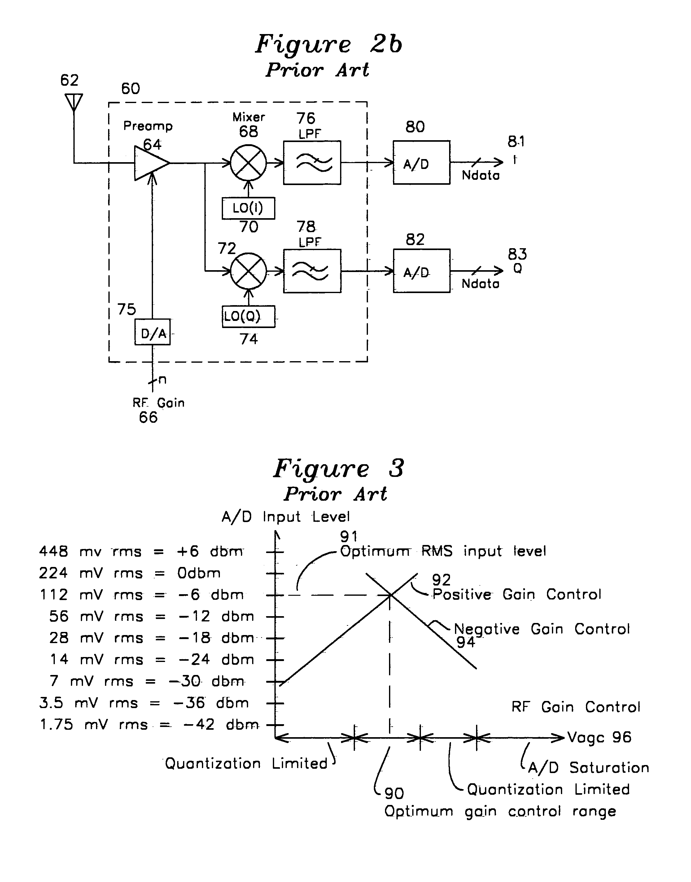
One of the characteristics of an RF receiver is gain control, and one of the limitations of the output of an RF receiver is saturation, whereby the signal level is amplified beyond the linear region of operation of the amplifier.

Method used


Image

  • Digital automatic gain control method and apparatus
  • Digital automatic gain control method and apparatus
  • Digital automatic gain control method and apparatus

Examples


Embodiment Construction

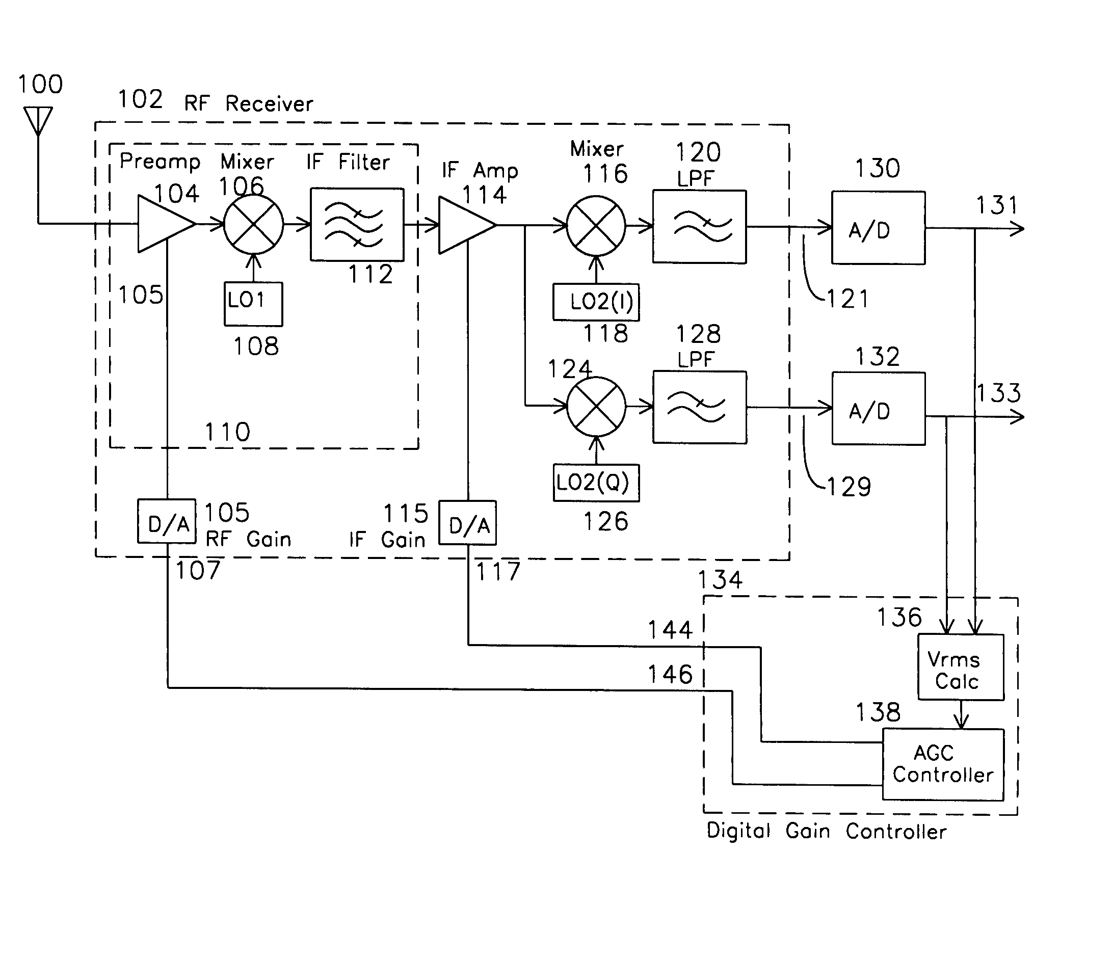
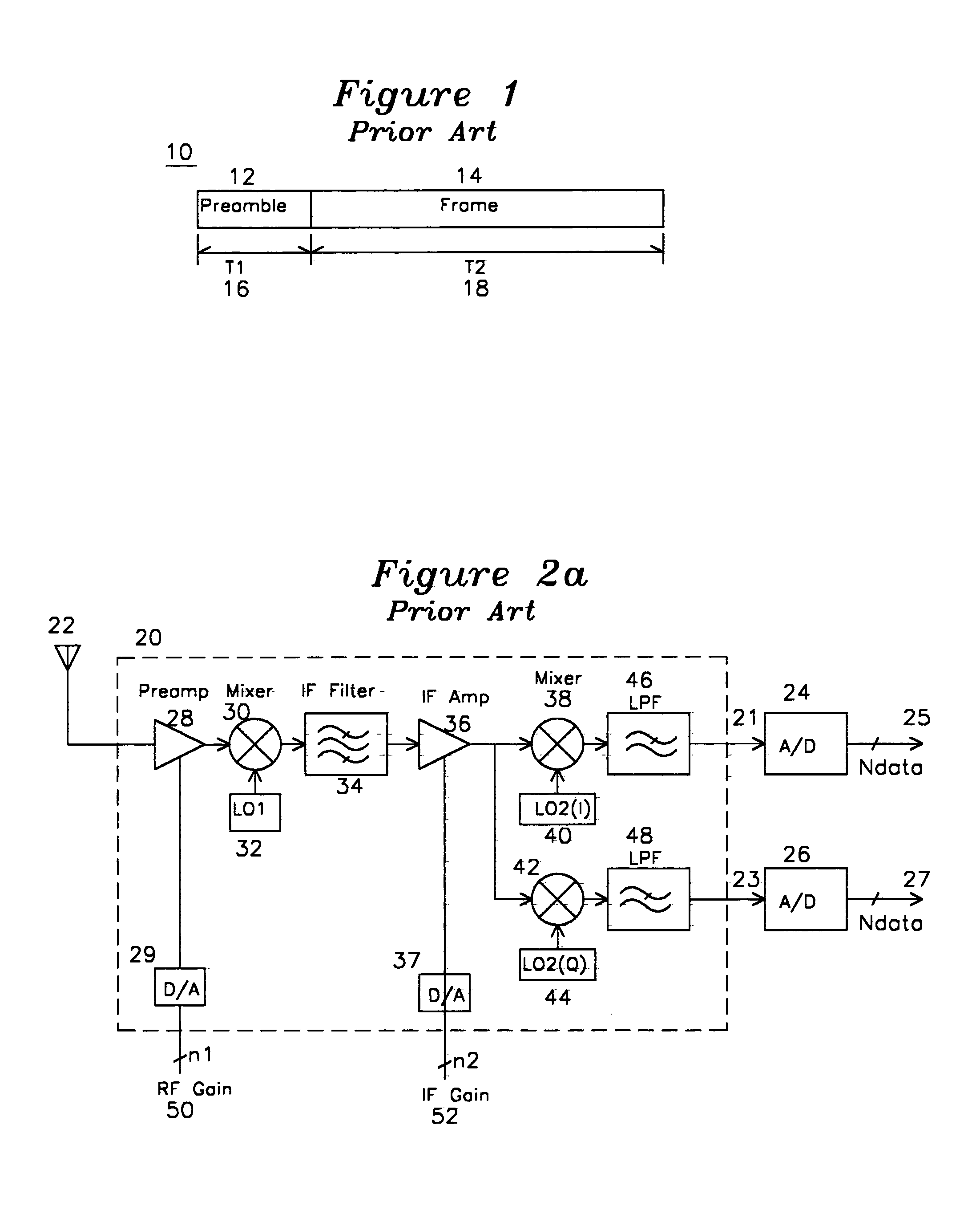
[0021]FIG. 4 shows an antenna 100 coupled to a prior art receiver 102 with a digital AGC controller 134. The operation of the RF receiver 102 is identical to either the heterodyne receiver 20 of FIG. 2a, or the direct conversion receiver 60 of FIG. 2b.

[0022]For a heterodyne receiver, the antenna 100 signal is applied to a preamplifier 104 having a digital gain control input 107 which converts the digital gain control to an analog voltage to control the adjustable gain preamplifier 104. The amplified signal is applied to a mixer 106, and mixed with the output of a local oscillator 108 which is offset from the center frequency of the wireless signal by an intermediate frequency (IF). The mixer 106 generates a signal at this IF which is passed on to the IF filter 112 and variable gain IF amplifier 114 having a gain control input 117 which produces a gain control signal for IF amplifier 114 with D / A converter 115. The IF amplifier 114 applies the amplified signals to the quadrature mix...


PUM


Abstract

An RF receiver which produces quadrature digitized outputs and has a gain control is coupled to a digital gain controller which converts the quadrature digitized outputs into an rms voltage, and iterates over a finite number of steps to quickly control the gain to a level sufficient to achieve subsequent digital signal processing without limitations caused by insufficient dynamic range or nonlinear saturation effects caused by insufficient signal or excessive signal at the A / D input, respectively.

Description

FIELD OF THE INVENTION[0001]This invention relates to the control of a wireless RF front end comprising mixers and amplifiers, where the RF front end, also known as an RF receiver, has a gain control input and the RF receiver produces a baseband output which is sampled by an A / D converter. The invention specifically relates to a method and apparatus for controlling the RF receiver gain by using the baseband output A / D converter outputs.BACKGROUND OF THE INVENTION[0002]RF amplifiers, mixers, and baseband converters are well known in the art of high frequency signal processing. One of the characteristics of an RF receiver is gain control, and one of the limitations of the output of an RF receiver is saturation, whereby the signal level is amplified beyond the linear region of operation of the amplifier. Typically, in an RF receiver, each successive stage generates signal gain, and in a digital signal processing system which accepts as input the A / D outputs of the RF receiver. For best...

Claims


Application Information

Patent Timeline
IPC IPC(8): H04L27/08
CPCH03G3/3068H03G3/3078
Inventor VENKATESH, NARASIMHANRAO, SATYASANKABATHULA, DHARANI NAGA SAILAJAMURALI, PARTHA SARATHY
Owner SILICON LAB INC
Learn More