Device for generation of x-ray radiation with a cold electron source

a technology of cold electron source and x-ray radiation, which is applied in the direction of x-ray tube cathode assembly x-ray tube cooling, etc., can solve the problem that the vacuum in the inventive device housing cannot be maintained extremely high, and achieve good focusing of the electron beam and long life

Inactive Publication Date: 2008-06-17
SIEMENS AG
View PDF11 Cites 9 Cited by
  • Summary
  • Abstract
  • Description
  • Claims
  • Application Information

AI Technical Summary

Benefits of technology

[0010]An object of the present invention is to provide a device for generation of x-ray radiation, in particular for usage in a computed tomography apparatus that enables a good focusing of the electron beam and exhibits a long lifespan.
[0012]A cold electron source, in particular a field emission electron source, is thus used in the present device, in which cold electron source the electron current can be controlled via an electrical field applied to the electron source. A very fast reaction time for the electron emission (and thus also for the x-ray emission) is thereby achieved. Details with regard to the design and usage of such an electron source can, for example, be learned from the publication (cited above) by Y. Cheng et al. Due to the device arranged between the electron source and the x-ray tube to reduce the proportion of positive ions in the region of the else, bombardment of the surface of the electron source by such ions is prevented or at least significantly reduced. This increases the lifespan of the electron source considerably without hereby limiting the focusing capability of the electron beam on the x-ray target. Therefore an extremely high vacuum need not be maintained in the housing of the inventive device. Rather, a certain proportion of gas molecules for generation of positive ions by impacts with the electrons of the electron beam is desired, since these positive ions serve for neutralization of the repulsive forces of the electrons of the electron beam in the focusing region of the electron beam, i.e. in particular in the region in front of the x-ray target. Due to the reduction of the space charge effect (i.e. the mutual repulsion of the electrons) in this region, the electron beam retains its sharp focusing and enables a small focus on the x-ray target, even given a lower anode potential and high electron current.

Problems solved by technology

Therefore an extremely high vacuum need not be maintained in the housing of the inventive device.

Method used


Image

  • Device for generation of x-ray radiation with a cold electron source
  • Device for generation of x-ray radiation with a cold electron source
  • Device for generation of x-ray radiation with a cold electron source

Examples


Embodiment Construction

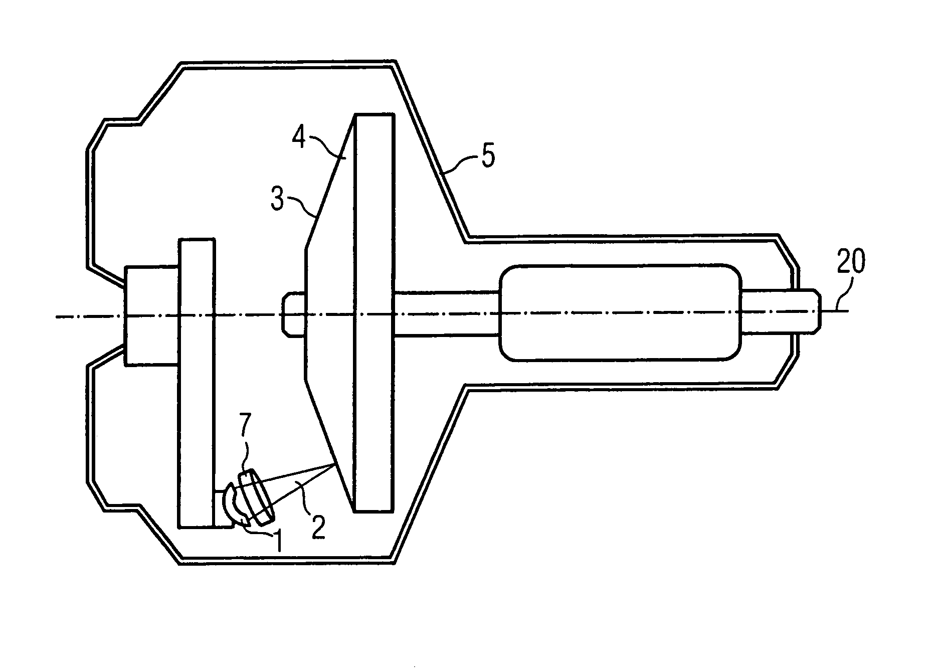
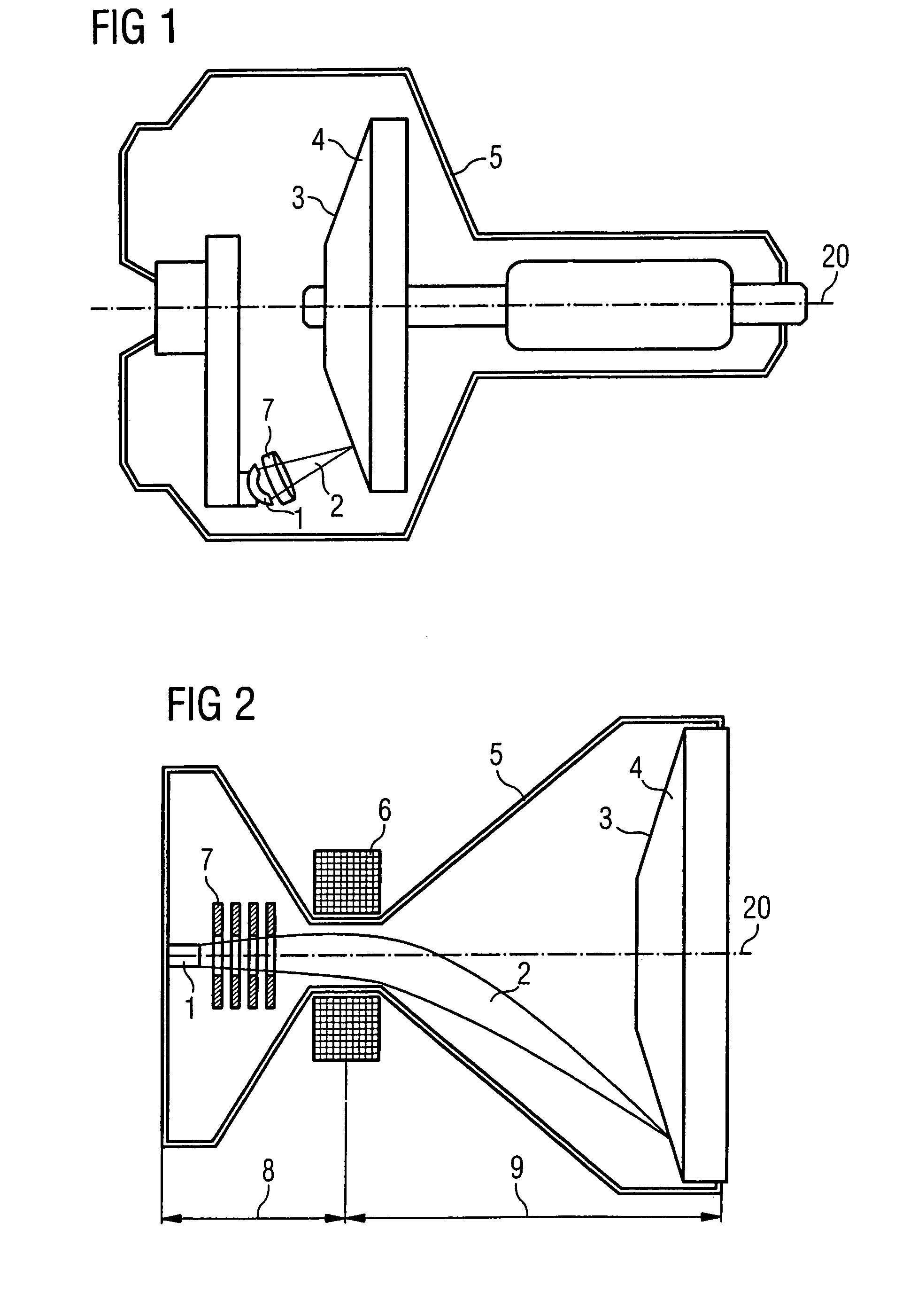
[0024]FIG. 1 schematically shows an example for an embodiment of the present device in which a rotating x-ray target 3 is used as an anode. The x-ray target 3 rotating around the rotation axis 20 and the cold electron source 1 are arranged in an evacuable housing 5. The cold electron source 1 exhibits a concave surface with which the emitted electron beam 2 is already focused onto the x-ray target 4. The electron emission ensues by the application of a suitable electrical field at the electron source 1, as is known in the prior art for such electron sources. A circular focal band 4 is generated on the x-ray target 3 via the rotation of the x-ray target 3 as an anode onto which the electrons of the electron beam 2 are accelerated, so the local temperature load is better distributed. Due to the striking electrons, the characteristic x-ray radiation is generated at the impact point. The characteristic x-ray radiation exits from the x-ray tube via a window (not shown) of the housing 5. ...


PUM


Abstract

A device for generation of x-ray radiation has one or more cold electron sources as a cathode and at least one x-ray target as an anode that are arranged in an evacuable housing. Upon application of an electrical voltage between cathode and anode, electrons emitted from the electron source are accelerated in an electron beam onto the x-ray target. A device for reduction of the proportion of positive ions in the region of the electron source is arranged between the electron source and the x-ray target in the housing. The device exhibits a long lifespan with good focusing capability and fast modulation capability of the electron beam.

Description

BACKGROUND OF THE INVENTION[0001]1. Field of the Invention[0002]The present invention concerns a device for generation of x-ray radiation, in particular for usage in a computed tomography apparatus, the device being of the type having an evacuable housing in which one or more cold electron sources are arranged as a cathode and at least one x-ray target is arranged as an anode, such that upon application of an electrical voltage between the cathode and the anode, electrons emitted by the electron source are accelerated in an electron beam onto the x-ray target.[0003]2. Description of the Prior Art[0004]Devices for generation of x-ray radiation are used, for example, in medical diagnostics in order to acquire radiographic images or, in the case of computed tomography (CT), images of the inside of the body of a patient. The requirements for x-ray tubes used in computed tomography have steadily grown with the manifold possibilities of computed tomography. Modern computed tomography syst...

Claims


Application Information

Patent Timeline
Patent Type & Authority Patents(United States)
IPC IPC(8): H01J35/00
CPCH01J3/00H01J35/065H01J35/14H01J35/26H01J35/305H01J2235/062H01J2235/066H01J2235/1212H01J2235/162H01J2235/168H01J35/147
Inventor HEMPEL, ECKHARDMATTERN, DETLEFPOPESCU, STEFAN
Owner SIEMENS AG
Why Eureka
Try Eureka