Objective lens holder, objective lens driving device including same and optical disk read/write device

a technology of optical disk and drive device, which is applied in the direction of optical elements, record information storage, instruments, etc., can solve the problems of low strength of inability to provide beam diameter limiting means, and achieve high-speed read/write operations. , the effect of high rigidity

Inactive Publication Date: 2008-06-24
SHARP KK
View PDF26 Cites 10 Cited by
  • Summary
  • Abstract
  • Description
  • Claims
  • Application Information

AI Technical Summary

Benefits of technology

[0016]The conventional objective lens holder has been arranged such that the beam diameter limiting means is provided so as to be sandwiched between protrusions that stick out perpendicular to the internal wall surfaces of the cavity. For this reason, according to the conventional arrangement, the beam diameter limiting means is low in strength (rigidity). However, according to the foregoing arrangement, the beam diameter limiting means is not provided so as to be sandwiched between the protrusions that stick out perpendicular to the internal wall surfaces of the cavity. That is, the cavity is surrounded with the internal wall surfaces facing each other so that the space between the internal wall surfaces gradually increases from the opening of the beam diameter limiting means toward the entrance or the exit. This causes the beam diameter limiting means to be thicker walled as compared with the conventional beam diameter limiting means. Therefore, the beam diameter limiting means becomes more resistant to oscillation than the conventional beam diameter limiting means.
[0017]This causes the beam diameter limiting means to be stronger than the conventional beam diameter limiting means. Therefore, the foregoing arrangement makes it possible to cause the objective lens holder to be more rigid than the conventional objective lens holder.
[0018]Accordingly, the foregoing arrangement makes it possible to provide a highly rigid objective lens holder. Further, since the beam diameter limiting means is rigid, the beam diameter limiting means never becomes a source of resonant oscillation. This allows high-speed read / write operations.
[0022]According to the foregoing arrangement, since the objective lens driving device includes the foregoing objective lens holder, the objective lens driving device becomes highly rigid and therefore exhibits a high resonant frequency. This brings about an effect of realizing a wide-bandwidth servo characteristic.
[0024]Furthermore, since the optical disk read / write device of the present invention includes the foregoing objective lens driving device, the optical disk read / write device allows high-speed read / write operations.

Problems solved by technology

For this reason, according to the conventional arrangement, the beam diameter limiting means is low in strength (rigidity).
However, according to the foregoing arrangement, the beam diameter limiting means is not provided so as to be sandwiched between the protrusions that stick out perpendicular to the internal wall surfaces of the cavity.

Method used


Image

  • Objective lens holder, objective lens driving device including same and optical disk read/write device
  • Objective lens holder, objective lens driving device including same and optical disk read/write device
  • Objective lens holder, objective lens driving device including same and optical disk read/write device

Examples


first embodiment

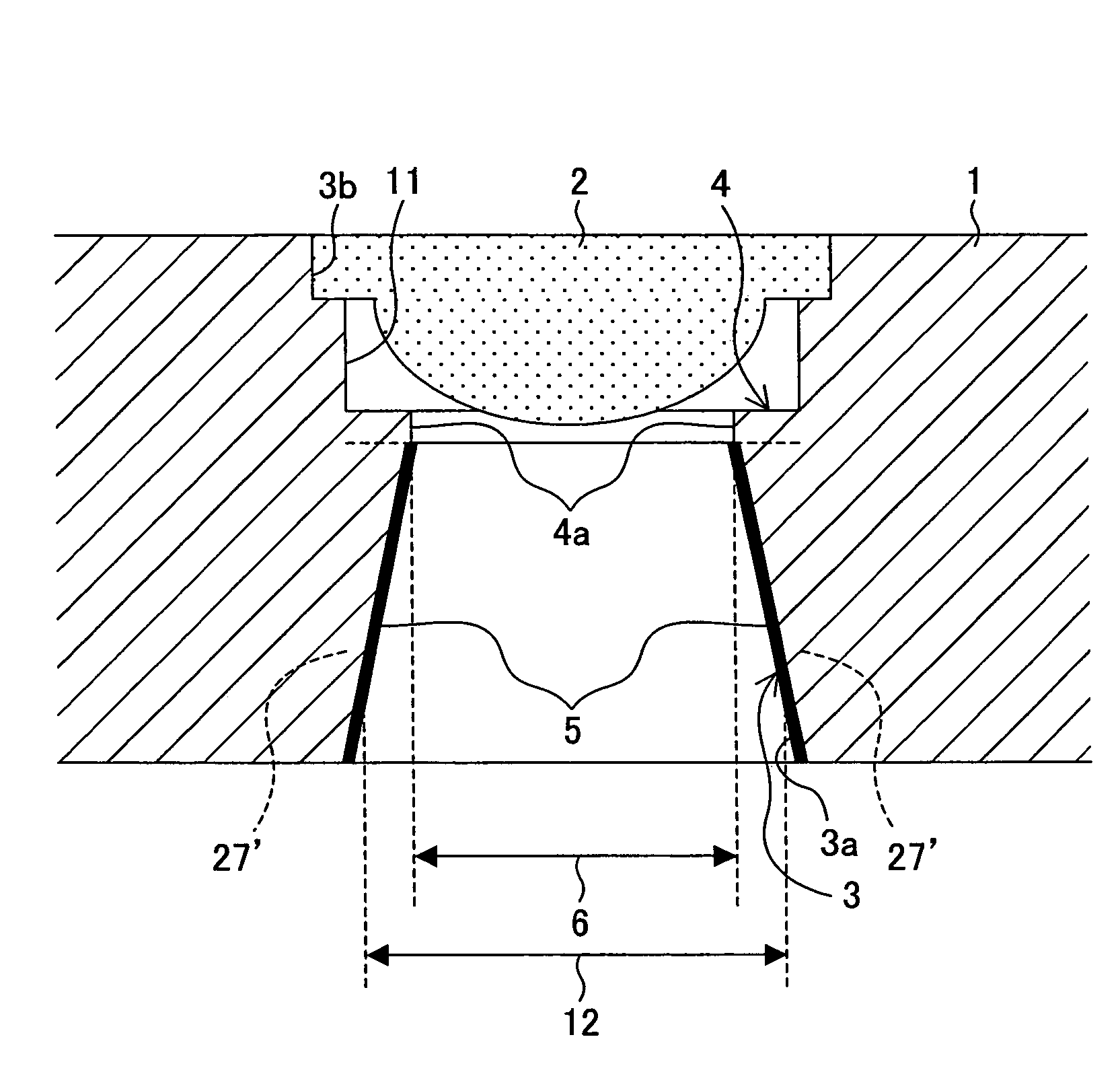
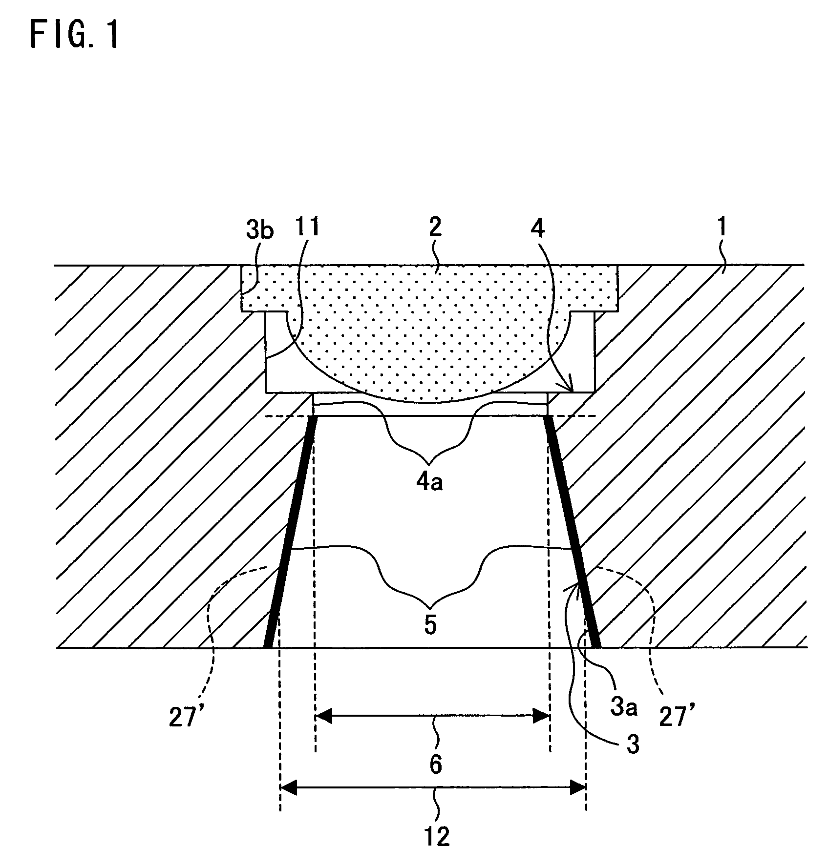
[0037]One embodiment of the present invention will be described below with reference to FIGS. 1 to 4. FIG. 1 is a cross-sectional view schematically illustrating an arrangement of an objective lens holder according to the present embodiment.

[0038]As illustrated in FIG. 1, an objective lens holder 1 includes a cavity 3. The cavity 3 has an entrance 3a and an exit 3b. An incident light beam 12 enters the entrance 3a and exits from the exit 3b. Provided on the exit 3b side of the cavity 3 is an objective lens mounting part 11 for housing and mounting an objective lens 2 therein. The cavity 3 includes a function of guiding, to the objective lens 2, the incident light beam 12 entering the entrance 3a. The light beam passing through the cavity 3 passes through the objective lens 2, and then is emitted from the objective lens holder 1.

[0039]Further, deeply inside the cavity 3, an aperture (beam diameter limiting means) 4 is provided on one side of the objective lens 2 facing the entrance 3...

second embodiment

[0070]Another embodiment of the present invention will be described below with reference to FIGS. 5 to 7. FIG. 5 is a cross-sectional view schematically illustrating an arrangement of an objective lens holder according to the present embodiment.

[0071]As illustrated in FIG. 5, an objective lens holder 19 includes the cavity 3. The cavity 3 has the entrance 3a and the exit 3b. The incident light beam 12 enters the entrance 3a and exits from the exit 3b. Provided on the entrance 3b side of the cavity 3 is the objective lens mounting part 11 for mounting the objective lens 2 therein.

[0072]Further, deeply inside the cavity 3, the aperture 4 is provided on one side of the objective lens 2 facing the entrance 3a. The aperture 4 has the opening 4a whose diameter is as large as the effective diameter of the objective lens 2. Therefore, the aperture 4 limits, to the effective diameter 6 of the objective lens, the diameter of the incident light beam 12 passing through the cavity 3 from the ent...

third embodiment

[0092]Yet another embodiment of the present invention will be described below with reference to FIG. 9. FIG. 9 is a perspective view schematically illustrating an arrangement of an objective lens driving device according to the present embodiment.

[0093]As illustrated in FIG. 9, the objective lens driving device 100 includes a driving unit section, a supporting mechanism section, and a fixing section including a magnetic circuit.

[0094]Prior to the detailed description of the objective lens driving device, x, y, and z directions in a three-dimensional orthogonal coordinate system are defined as follows. As illustrated in FIG. 9, the x direction is defined as a direction in which plate springs 32 extend. The plate springs 32 movably support the diving unit section. The x direction corresponds to a track tangential direction of the optical disk when the objective lens driving device carries out read / write operations of the optical disk. The x direction is hereinafter referred to as “tan...


PUM


Abstract

An objective lens holder of the present invention includes: (i) a cavity, having an entrance and an exit, which guides, to an objective lens, an incident light beam entering the entrance, the exit being provided on a side of the cavity where the objective lens is housed; and (ii) an aperture having an opening for limiting, to an effective diameter of the objective lens, a beam diameter of the incident light beam passing through the cavity. The cavity is surrounded with internal wall surfaces facing each other so that space between the internal wall surfaces gradually increases from the opening of the aperture toward the entrance or the exit. This makes it possible to provide a highly rigid objective lens holder that allows high speed read / write operations.

Description

[0001]This Nonprovisional application claims priority under 35 U.S.C. § 119(a) on Patent Application No. 354584 / 2004 filed in Japan on Dec. 7, 2004, the entire contents of which are hereby incorporated by reference.FIELD OF THE INVENTION[0002]The present invention relates to an objective lens holder, an objective lens driving device, and an optical disk read / write device.BACKGROUND OF THE INVENTION[0003]In order to precisely read / write an optical disk such as a CD, a DVD, or a BD (blue-ray disc), it is necessary to (i) cause light emitted from a light source to enter an objective lens so that a very small beam spot is formed on the optical disk, and to (ii) cause the beam spot to follow a desired recording track while maintaining a shape of the beam spot.[0004]One of the components essential for realization of precise read / write of an optical disk is an aperture, i.e., an opening provided in an objective lens holder. An arrangement of the aperture is described, for example, in Paten...

Claims


Application Information

Patent Timeline
Patent Type & Authority Patents(United States)
IPC IPC(8): G02B7/02
CPCG11B7/0935
Inventor INUI, TOSHIHARUKAWANO, TAKASHI
Owner SHARP KK
Why Eureka
Try Eureka