High performance electrical connector

a high-performance, electrical connector technology, applied in the direction of coupling contact members, coupling device connections, connection contact member materials, etc., can solve the problems of connector sliding over the surface, limited density of contactors so made, and limited miniaturization density of mechanically stamped and formed springs, so as to reduce the self inductance of the connector of the present invention, the effect of less magnetic flux penetration and low self inductan

Inactive Publication Date: 2008-07-01
CENTIPEDE SYST
View PDF14 Cites 73 Cited by
  • Summary
  • Abstract
  • Description
  • Claims
  • Application Information

AI Technical Summary

Benefits of technology

[0030]A further advantage of the present invention is provided by a tubular connector with helical prongs on a first end that engage a first ball and helical prongs on a second and opposing end that engage a second ball, whereby the prongs of the first end resiliently pull the first ball toward the second ball. This advantage enables use of an array of such connectors to attach an electronic device to a substrate without need for a mechanical retaining component to apply force urging the device toward the substrate.
[0031]Yet another advantage is provided by the present invention embodied in a connector that has a low self inductance. Thin laser-cut grooves through the tube allow less magnetic flux penetration into the interior of the tube than a connector made of a helical wire spring. The self inductance of the connector of the present invention may be further reduced by making the helical prongs short, as they extend a small distance from a solid girth around the tubular connector. These and other aspects of the present invention allow a high performance connector.
[0032]Depending upon the embodiment, one or more of these benefits may exist. These and other benefits have been described throughout the present specification and more particularly below.
[0033]Various additional objects, features, and advantages of the present invention can be more fully appreciated with reference to the detailed description and accompanying drawings that follow.

Problems solved by technology

Miniaturization and density of the mechanically stamped and formed springs are limited by present capabilities to a certain size.
Although advances continue to be made in the manufacturing art of stamping and forming springs, sockets with contactors so made are limited in density by the complexity of stamping and forming vary small miniaturized springs.
Because of small compliance in a vertical direction, a miniature stamped and formed spring may be unable to accommodate motion of a contactor support relative to a ball mated to it, thereby allowing vibration, mechanical shock load and forces, flexure, and the like to cause the connector to slide over the surface of the ball.
It is known in the industry that repeated microscopic motion of one contact relative to a mating contact causes fritting or a build up of small, particle debris that can lead to contact failure.
As connector assemblies are miniaturized, the molding and assembly process are increasingly difficult and costly, thereby limiting the extension of connectors based on formed spring contacts to very high densities.
The clamping force needed by BGA sockets that make contact by applying force vertically is an increasing problem as the number of contact bumps increases into the thousands.
Further, at higher frequencies and clock speeds, the size and the self inductance of connectors are becoming an important limitation to system performance.
If the detents and balls are of non-matching or of non-uniform size, looseness, non-uniform gripping force and loss of gripping ability may result.

Method used


Image

  • High performance electrical connector
  • High performance electrical connector
  • High performance electrical connector

Examples


Embodiment Construction

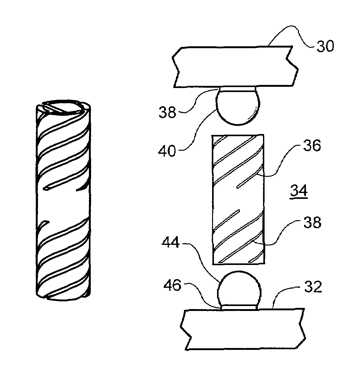
[0046]According to the invention, a high performance connector is provided for making reliable electrical connection to miniature and typically closely spaced terminals on an electronic device. More particularly, embodiments of the present invention provide a cylindrical metal tube that is cut in a helical pattern of slots into several prongs that are adapted to contact a terminal post around its circumference and to provide electrical contact thereto.

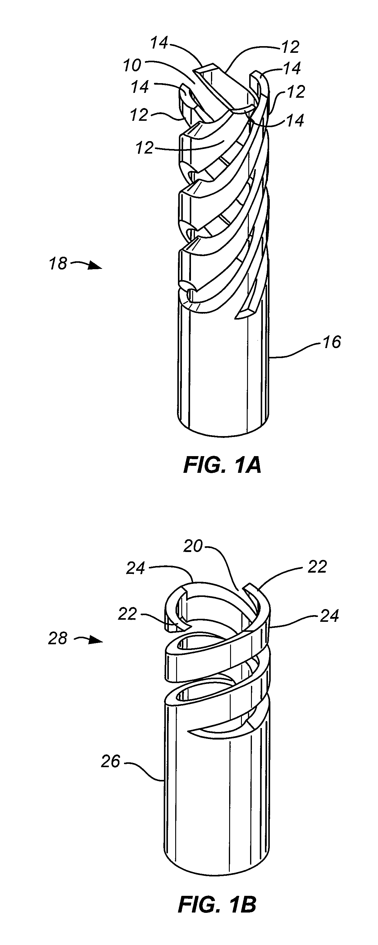
[0047]As illustrated in FIG. 1A, connector 18 comprises a hollow cylindrical metal tube which is cut through by helical slots 10 to form in this instance four canted prongs 12 terminated in four tips 14. Prongs 12 are held in place by cylindrical collar region 16 in the unsliced portion of the tube. The prongs are adapted to grip a post inserted along the axis of connector 18. The posts (not shown) preferably have a ball tip. However, a cylindrical or frustoconical tip having an outer diameter in the mating region that is slightly grea...


PUM


Abstract

A socket connector for connecting a post or ball wherein the female element grips the post with resilient prongs with end tips at low insertion force but positive contact is maintained and wherein attempted withdrawal is normally inhibited by increasing force applied to the post by the female element in response to the withdrawal force. The female element comprises a tube of resilient conductive material that has been sliced or helically partitioned into opposing helical prongs so as to allow the prongs of the connector to spirally open around the post or ball-like bump and mechanically grip the post or bump as the post or bump is inserted along the longitudinal axis of the tube. The tubular element may be made by forming helical prongs in the end of a tube in helical cuts from about a mid section to one end of the tube.

Description

CROSS-REFERENCES TO RELATED APPLICATIONS[0001]This application claims the benefit of U.S. Provisional Application Ser. No. 60 / 774,725 filed Feb. 17, 2006, on behalf of Decision Track LLC, a Subchapter S corporation sharing common ownership with the present assignee. The content of said Provisional Application is incorporated herein by reference in its entirety.STATEMENT AS TO RIGHTS TO INVENTIONS MADE UNDER FEDERALLY SPONSORED RESEARCH AND DEVELOPMENT[0002]Not applicableREFERENCE TO A “SEQUENCE LISTING,” A TABLE, OR A COMPUTER PROGRAM LISTING APPENDIX SUBMITTED ON A COMPACT DISK[0003]Not applicableBACKGROUND OF THE INVENTION[0004]This invention relates to miniature electrical connectors, as for example ball grid array (BGA) connectors, including connectors having pin dimensions of less than 1 millimeter in diameter and pin pitches of less than two millimeters. One or more embodiments of the present invention relate to a high performance electrical connector, that is a connector for ...

Claims


Application Information

Patent Timeline
Patent Type & Authority Patents(United States)
IPC IPC(8): H01R12/00H01R12/71H01R24/38
CPCH01R13/2407H01L2224/16225H01L2924/15312H01R12/7082H01R12/73H01R13/11H01R13/111H01R13/24H01R4/60H01R4/58
Inventor DISTEFANO, THOMAS H.
Owner CENTIPEDE SYST
Why Eureka
Try Eureka