
Susceptor

a technology of suceptor and film, applied in the direction of chemically reactive gases, crystal growth process, coating, etc., can solve the problems of fine cracks in the film, short lifetime, wafer coming off the recess, etc., and achieve the effect of not adversely affecting the wafer, long lifetime, and stably used

Active Publication Date: 2008-07-01
COORSTEK INC
View PDF6 Cites 394 Cited by
  • Summary
  • Abstract
  • Description
  • Claims
  • Application Information

AI Technical Summary

Benefits of technology

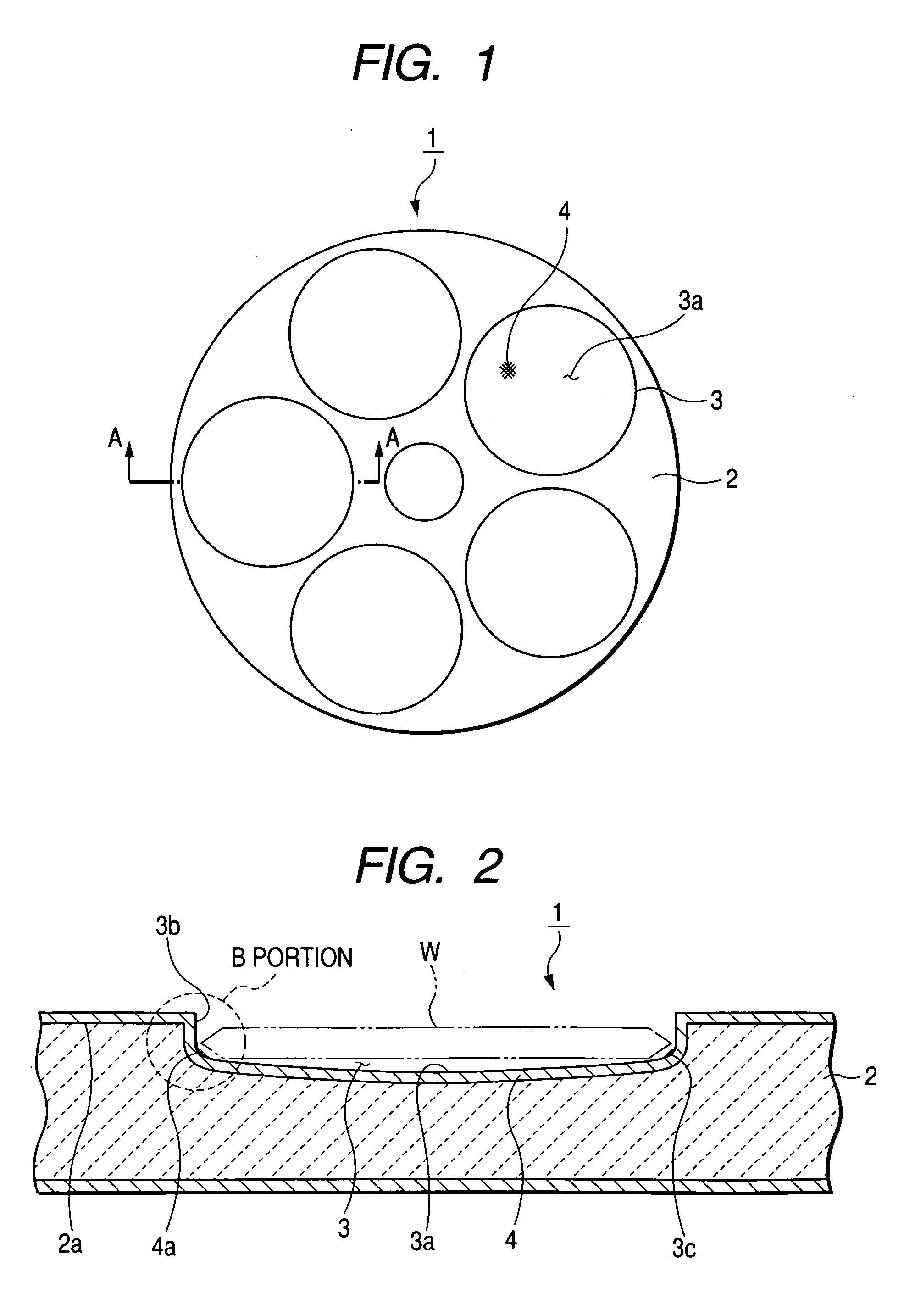
"The invention provides a susceptor that can hold a semiconductor wafer without cutting its surface or causing cracks at the lower portion of its outer circumference. The susceptor has a recess where the wafer is mounted, with a round portion and a ring-shaped SiC crystal growth surface portion. The surface roughness of the recess is controlled to prevent fine cracks. The susceptor can also homogenize the epitaxial layer of the wafer and does not agglomerate impurity components. Overall, the invention provides a stable and uniform heat treatment for the wafer."

Problems solved by technology

Furthermore, when the coated surface is polished and used as shown in the JP-A-7-335572, stress is concentrated during the polishing process in the vicinity of a boundary portion between a bottom surface portion of the recess where a semiconductor wafer is mounted on and a vertical portion thereof to cause fine cracks in the film.
Furthermore, in some cases, owing to the thermal stress during the heat treatment, with the fine crack as a starting point, cracks as shown in FIG. 6 are generated on the coated surface, resulting in a short lifetime.
Accordingly, there is a problem in that owing to a centrifugal force in association with a rotary motion of the susceptor and an influence of the gas, the wafer comes off the recess.
However, in this case, there is a problem in that since a partial temperature difference is formed in the wafer surface, the wafer cannot be performed uniformly heat treatment.
Furthermore, when it is used repeatedly, in the outer circumference portion, it is highly likely that impurity components agglomerate to adversely affect on the wafer.
In the latter case, since the gas flow in the outer circumference portion becomes excessively uniform to cause an abnormal growth protrusion in a deposition layer, for instance, on a downstream side of the gas, after the repetition use, the uniformity of the epitaxial layer of the wafer may be deteriorated.

Method used


Image

  • Susceptor
  • Susceptor
  • Susceptor

Examples


examples

[0058][Experiment 1]

Example 1

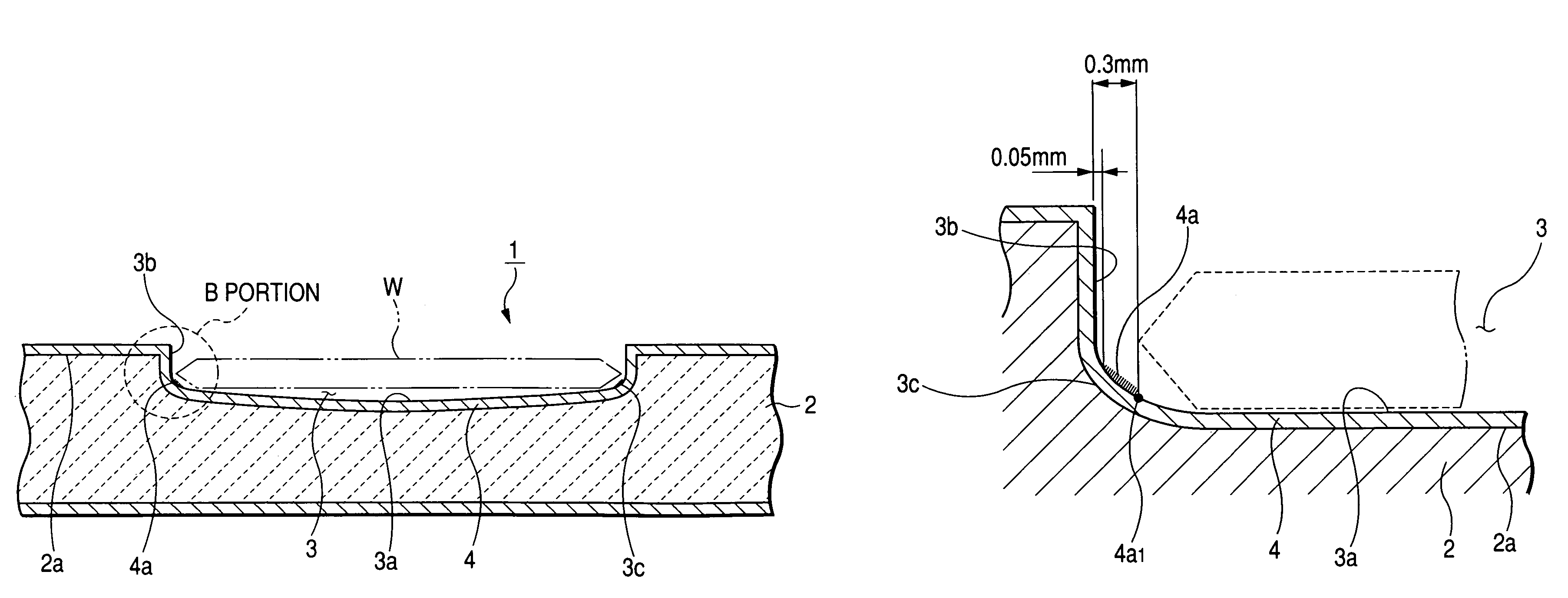
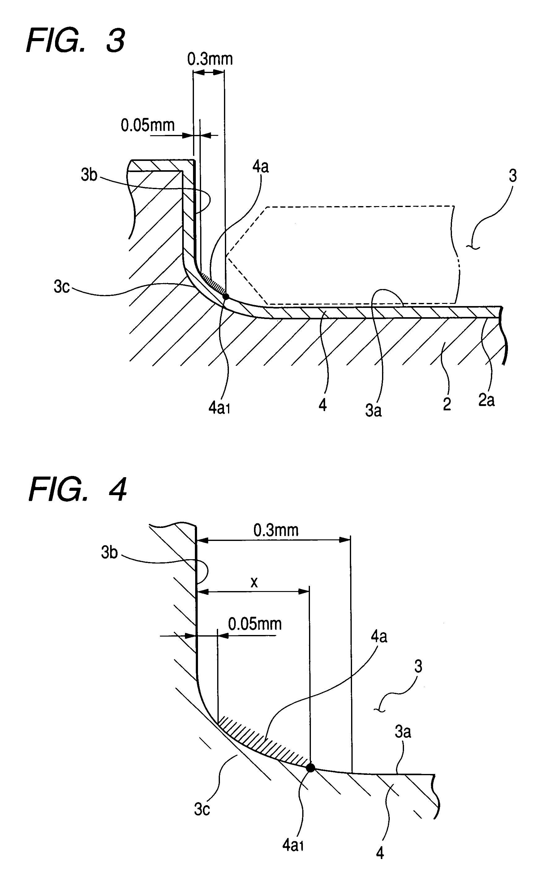
[0059]An isostatic carbon base material machined into a susceptor shape having one recess was coated with SiC having surface roughness Ra of 7.2 μm. A mounting surface of the recess excluding an area, which is defined 0.3 mm from an outer circumference side thereof as a non-polished portion was ground and polished with a rotary polishing machine with diamond abrasive grains of #500 or less to prepare a susceptor.

example 2

[0060]A susceptor was prepared in a similar manner to example 1 except that the non-polished portion on the outer circumference side of the recess was set at 0.05 mm.

example 3

[0061]A susceptor was prepared in a similar manner to example 1 except that abrasive grains of the rotary polishing machine were set at #40 or less.


PUM

PropertyMeasurementUnit
distanceaaaaaaaaaa
arithmetic average roughnessaaaaaaaaaa
surface roughness Raaaaaaaaaaa

Abstract

A susceptor at least a surface thereof being coated with SiC, includes a recess where an wafer is mounted, the recess having an round portion disposed on a lower portion of an outer circumferential portion of the recess, a ring-shaped SiC crystal growth surface portion provided within the round portion in a range of 0.05 mm or more and 0.3 mm or less defined from an outer circumference vertical portion of the recess and a contact portion, where the susceptor contacts with the wafer on the recess, having a surface roughness Ra in a range of 0.5 μm or more and 3 μm or less.

Description

[0001]The present invention claims foreign priority to Japanese patent application No. 2004-285280, filed on Sep. 29, 2004 and No. 2004-085230, filed on Mar. 23, 2004, the contents of which are incorporated herein by references.BACKGROUND OF THE INVENTION[0002]1. Field of the Invention[0003]The invention relates to a susceptor, in particular, a susceptor in which a SiC film formed on a wafer pocket is partially left without polishing so as to be a SiC grain growth surface portion.[0004]2. Description of the Background Art[0005]A semiconductor device is manufactured through many manufacturing processes. As susceptors that are used in an epitaxial growth process of a semiconductor wafer, because of the low reactivity and high strength, a SiC member in which SiC is coated on a carbon base material is frequently used.[0006]There are a sheet-like susceptor in which a single wafer-housing recess is formed on a planar susceptor base material and a susceptor in which many recesses are forme...

Claims


Application Information

Patent Timeline
Patent Type & Authority Patents(United States)
IPC IPC(8): C23C16/00C23C16/458H01L21/205H01L21/306B81C99/00
CPCC23C16/4581C23C16/4584C30B25/12H01L21/68771H01L21/68735H01L21/68757H01L21/68764C30B31/14
Inventor YOKOGAWA, MASANARI
Owner COORSTEK INC
Learn More