
Practical laser induced breakdown spectroscopy unit

a breakdown spectroscopy and laser technology, applied in the field of laser induced breakdown spectroscopy, can solve the problems of limited field application, uncertain clumsiness, and relatively high energy consumption, and achieve the effect of being the easiest to reach

Active Publication Date: 2008-07-01
HITACHI HIGH TECH ANALYTICAL SCI FINLAND OY
View PDF26 Cites 48 Cited by
  • Summary
  • Abstract
  • Description
  • Claims
  • Application Information

AI Technical Summary

Benefits of technology

"The present invention is about a new laser-induced breakdown spectroscopy (LIBS) apparatus that is practical and applicable to field use. The apparatus includes a handheld unit with all essential components of a LIBS measurement arrangement. The invention also includes a combination of a solid laser medium and a Q-switch, focusing optics, and light collection optics. The apparatus is designed to be easy to use and access samples in difficult or inconvenient locations. The invention also includes a power source and a handheld probe with a separate part containing the Q-switch, focusing optics, and light collection optics. The use of a separate probe part allows for laser diode power control and enables samples and locations that would be difficult or inconvenient to reach with the whole handheld measurement apparatus to still be reached with the probe. The invention is based on the use of a passive Q-switch and the reduction of resonator loss through saturation effect. The use of Nd:YLF as the active (gain) medium and wavelength locking helps to stabilize the output wavelength of the laser diode and avoid temperature-dependent wavelength drift. The invention provides a practical and applicable LIBS measurement arrangement that is easy to use and access samples in difficult or inconvenient locations."

Problems solved by technology

A drawback of the known LIBS measurement devices is certain clumsiness and limited applicability to field use.
Passively Q-switched pulse lasers have been considered to only be suitable to benchtop analysers, because their energy consumption has been relatively high.

Method used


Image

  • Practical laser induced breakdown spectroscopy unit
  • Practical laser induced breakdown spectroscopy unit
  • Practical laser induced breakdown spectroscopy unit

Examples


Embodiment Construction

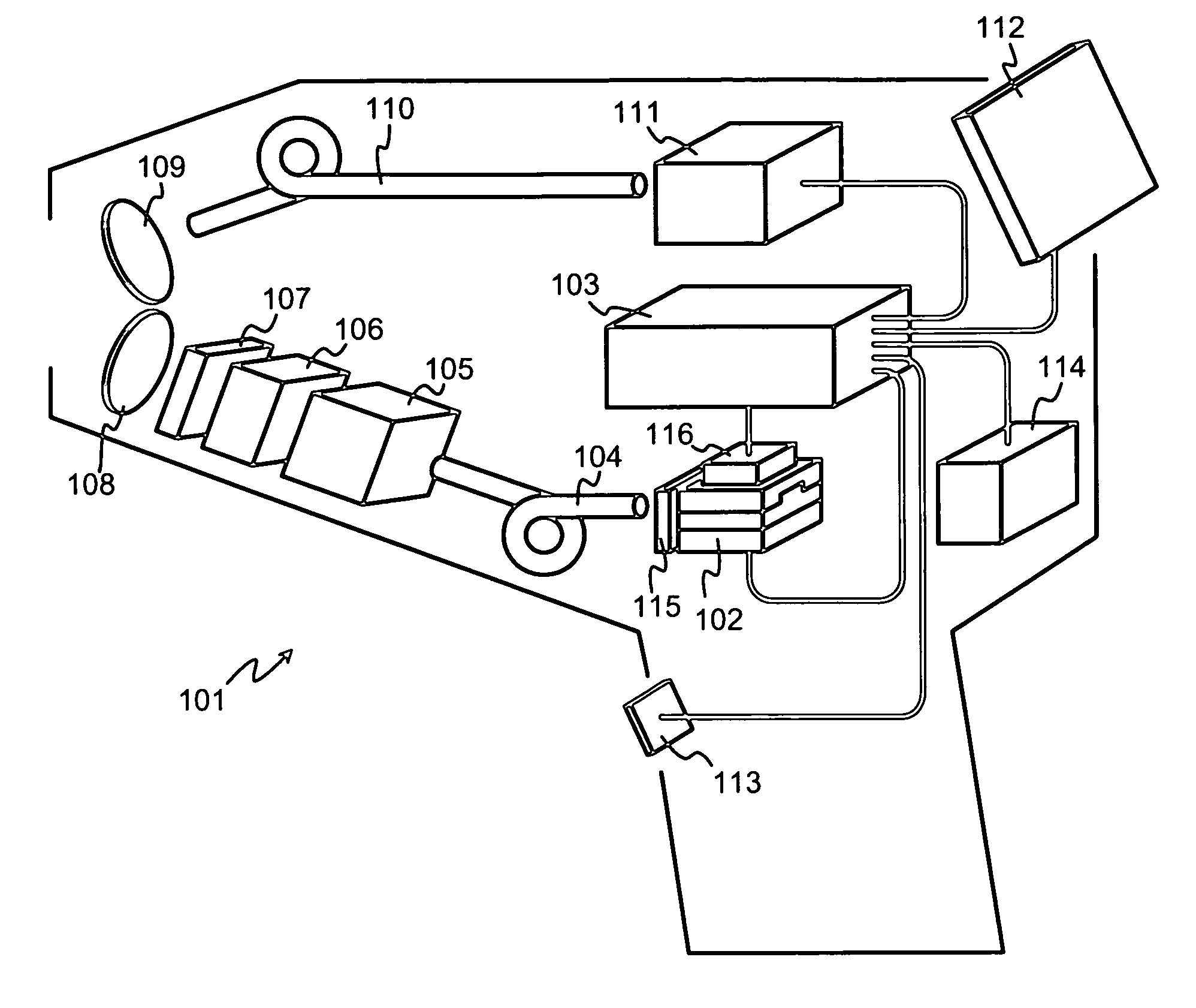
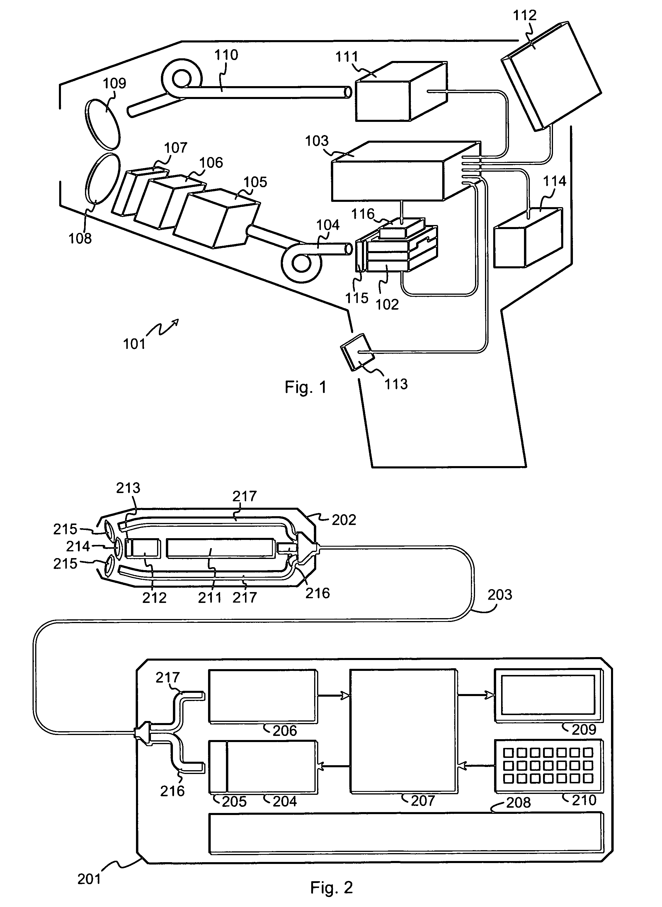
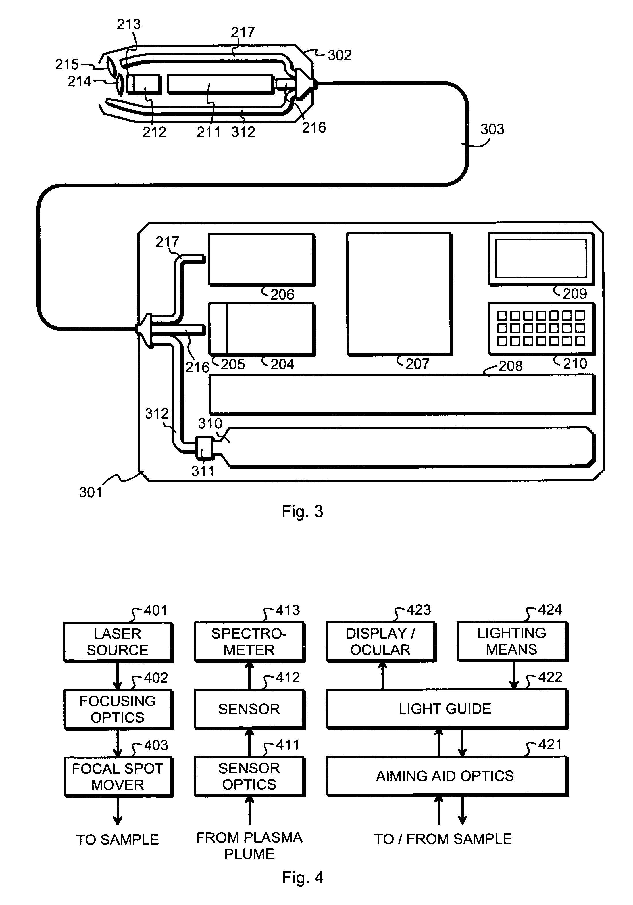
[0025]FIG. 1 illustrates schematically a handheld unit 101, which has a size and shape that enable a human user to easily carry it along in the purpose of making LIBS measurements. Inside the handheld unit 101 is a pump laser 102, which here is schematically shown as a laser diode. A controller 103 is arranged to control the operation of the pump laser 102. An optical fiber 104 conducts the laser light emitted by the pump laser 102 to a combination of a solid laser medium 105 and a Q-switch 106, which is typically a passive Q-switch but may also be an active one. Together the solid laser medium 105 and the Q-switch constitute a Q-switched pulse laser, the output pulses of which are directed through an outcoupling mirror 107 and focusing optics 108 towards a sample (not shown).

[0026]A person skilled in the art understands that the linear arrangement of the Q-switched pulse laser, which is schematically illustrated in FIG. 1, is not the only possible alternative. A linear arrangement ...


PUM

PropertyMeasurementUnit
absorption wavelengthsaaaaaaaaaa
temperatureaaaaaaaaaa
distanceaaaaaaaaaa

Abstract

An apparatus for performing laser-induced breakdown spectroscopy comprises a handheld unit with a pump laser and a controller. A combination of a solid laser medium and a Q-switch receive a laser beam from said pump laser. Focusing optics focus laser pulses from said combination to a focal spot at a sample. Light collection optics collect light from plasma induced of sample material by focused laser pulses. A spectrometer receives collected light and produces information describing its spectral distribution. A power source delivers electric power to other parts of the apparatus. The pump laser, combination, focusing optics, light collection optics, spectrometer and power source are parts of said handheld unit.

Description

TECHNICAL FIELD[0001]The invention concerns in general the technology of laser-induced breakdown spectroscopy. In particular the invention concerns the structure of an apparatus built for laser-induced breakdown spectroscopy measurements.BACKGROUND OF THE INVENTION[0002]For various applications, methods are needed for determining the material constitution of a sample. One of known methods is laser-induced breakdown spectroscopy (LIBS), which involves focusing a laser beam onto a surface of the sample with a high enough power density to transform a small part of the sample material into a state of plasma. Optical emissions from the plasma plume are collected with light collection optics, and the spectral distribution (i.e. intensity as a function of wavelength) of the collected optical emissions is analysed in a spectrometer that produces information in electronic form describing the spectral distribution. Since atomic and molecular constituents of sample materials have characteristi...

Claims


Application Information

Patent Timeline
Patent Type & Authority Patents(United States)
IPC IPC(8): G01N21/74G01J3/443
CPCG01N21/718G01N2201/0221
Inventor LINDFORS, PAMELAKRAPU, MIKKO
Owner HITACHI HIGH TECH ANALYTICAL SCI FINLAND OY
Learn More