Control system and method with constant maximum current for power converter protection

a control system and constant maximum current technology, applied in the field of integrated circuits, can solve the problems of affecting the protection of power converters, affecting the protection of rectifier components on the transformer secondary side, and affecting the operation of power conversion systems, etc., and achieves excellent compensation for the “delay to output”, easy adjustment of external resistors, and low standby power.

Inactive Publication Date: 2008-07-01
ON BRIGHT ELECTRONICS SHANGHAI
View PDF5 Cites 85 Cited by
  • Summary
  • Abstract
  • Description
  • Claims
  • Application Information

AI Technical Summary

Benefits of technology

[0019]Many benefits are achieved by way of the present invention over conventional techniques. For example, some embodiments can provide an excellent compensation for the “delay to output” by easily adjusting an external resistor. For example, the adjustment of the external resistor takes into account converter components external to a chip for PWM control. Certain embodiments allow a maximum current and a maximum power that are constant over a wide range of input voltage. Some embodiments consume a low standby power by sharing a resistor for a sensing system with a startup system and / or a brownout protection system. For example, the resistor is shared by a sensing system and a startup system. Certain embodiments provide an excellent compensation for the “delay to output” without sensing an input voltage. For example, the pin counts for a chip for PWM control is limited. In another example, the maximum width of a PWM signal is used to represent the input voltage. Different input voltages result in different maximum widths for the PWM signal, and the different maximum widths result in different effective threshold signals. Some embodiments provide an over-current protection that can effectively protect a power converter from excessive power, thermal run away, excessive current and / or voltage stress.

Problems solved by technology

The current flowing through the power switch and transformer winding may be limited by an OCP system.
If the OCP system is not effective, the current can reach a level at which damage to the power switch is imminent due to excessive current and voltage stress at switching or thermal run-away during operation.
Consequently, the rectifier components on the transformer secondary side are subject to permanent damage due to excessive voltage and current stress in many offline flyback converters.
This limitation on maximum power can protect the power converter from thermal run-away.
Some conventional OCP systems use an adjustable OCP threshold value based on line input voltage, but the actual limitation on maximum current and thus maximum power is not always constant over a wide range of line input voltage.
But the resistor 152 consumes significant power, which often is undesirable for meeting stringent requirements on low standby power.

Method used


Image

  • Control system and method with constant maximum current for power converter protection
  • Control system and method with constant maximum current for power converter protection
  • Control system and method with constant maximum current for power converter protection

Examples


Embodiment Construction

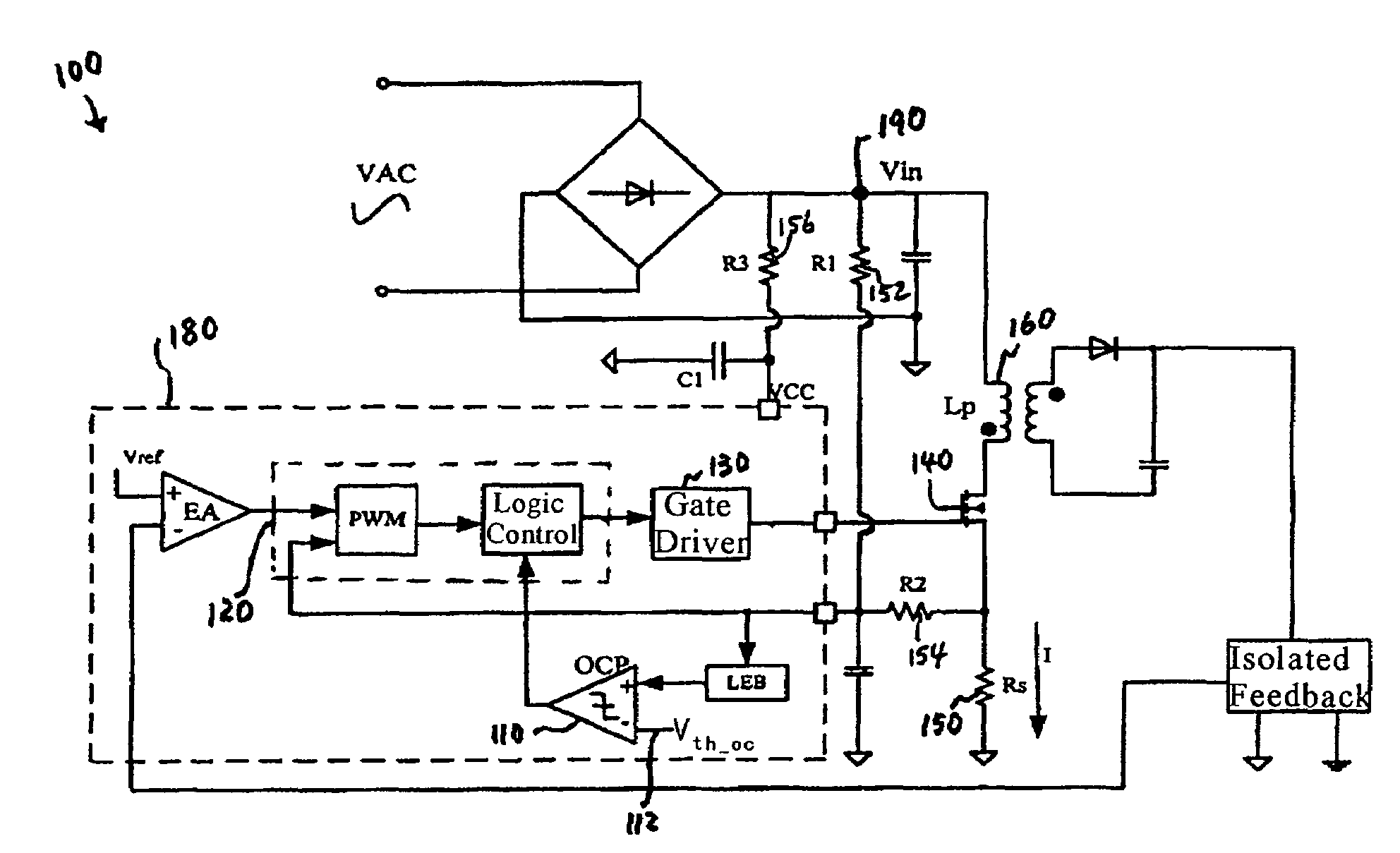
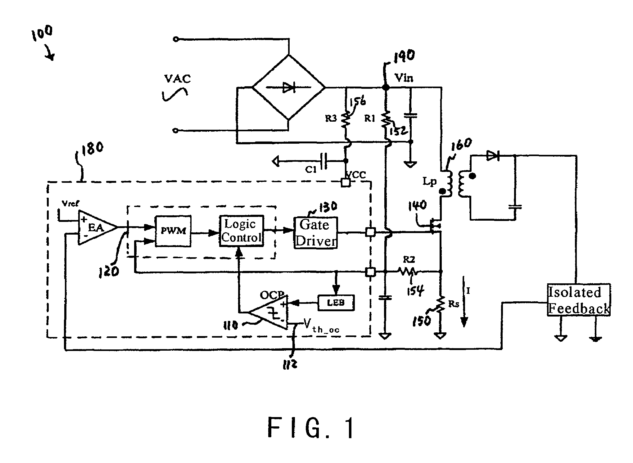
[0032]The present invention is directed to integrated circuits. More particularly, the invention provides a control system and method for over-current protection with constant maximum current. Merely by way of example, the invention has been applied to a power converter. But it would be recognized that the invention has a much broader range of applicability.

[0033]As shown in FIG. 1, the current limit is expressed as follows:

[0034]ILimit=Vi⁢⁢nLp×ton=Vth_ocRs(Equation⁢⁢1)

[0035]where ILimit represents the current limit. For example, the current limit is the current threshold for triggering over-current protection. Additionally, Vin is the input line voltage at node 190, and Vth—oc is the voltage level at an input terminal 112 of the OCP comparator 110. Rs is the resistance of the resistor 150, and Lp is the inductance of the primary winding 160. Moreover, ton represents on time of the power switch 140 for each cycle. Accordingly, the maximum energy ε stored in the primary winding 160 i...


PUM


Abstract

System and method for protecting a power converter. The system includes a first comparator configured to receive a threshold signal and a first signal and to generate a comparison signal. The first signal is a sum of a second signal and a third signal, and the third signal is associated with an input current for a power converter. Additionally, the system includes a pulse-width-modulation generator configured to receive the comparison signal and generate a modulation signal in response to the comparison signal, and a switch configured to receive the modulation signal and control the input current for the power converter. An amplitude for the first signal becomes larger if an amplitude for the input voltage becomes larger. The second signal is generated by receiving an input voltage for the power converter, converting the received input voltage to a fourth signal, and converting the fourth signal to the second signal.

Description

CROSS-REFERENCES TO RELATED APPLICATIONS[0001]This application claims priority to Chinese Patent Application No. 200510029016.6, filed Aug. 18, 2005, entitled “Control System and Method with Constant Maximum Current for Power Converter Protection,” by inventors Lieyi Fang, Shifeng Zhao, Bo Li, and Zhiliang Chen, commonly assigned, incorporated by reference herein for all purposes.[0002]Additionally, this application is related to U.S. patent application Ser. No. 11 / 051,242, commonly assigned, incorporated by reference herein for all purposes.STATEMENT AS TO RIGHTS TO INVENTIONS MADE UNDER FEDERALLY SPONSORED RESEARCH OR DEVELOPMENT[0003]NOT APPLICABLEREFERENCE TO A “SEQUENCE LISTING,” A TABLE, OR A COMPUTER PROGRAM LISTING APPENDIX SUBMITTED ON A COMPACT DISK[0004]NOT APPLICABLEBACKGROUND OF THE INVENTION[0005]The present invention is directed to integrated circuits. More particularly, the invention provides a control system and method for over-current protection with constant maxim...

Claims


Application Information

Patent Timeline
Patent Type & Authority Patents(United States)
IPC IPC(8): H02H7/00
CPCH02M1/32H02M3/33507
Inventor FANG, LIEYIZHAO, SHIFENGLI, BOCHEN, ZHILIANG
Owner ON BRIGHT ELECTRONICS SHANGHAI
Why Eureka
Try Eureka