Optical pickup device and optical disk playback device provided therewith

a pickup device and optical disk technology, applied in the direction of optical recording/reproducing/erasing methods, instruments, mechanical recording, etc., can solve the problems of increasing the manufacturing cost of the device, the structure of the optical disk playback and recording device becomes more complicated, and the device cannot be made smaller

Inactive Publication Date: 2008-07-01
FUNAI ELECTRIC CO LTD
View PDF12 Cites 4 Cited by
  • Summary
  • Abstract
  • Description
  • Claims
  • Application Information

AI Technical Summary

Benefits of technology

[0018]In this configuration, the wait time required for moving the optical pickup device is dispensed with, and transition from replaying data on one recording surface to replaying data on another recording surface can be performed smoothly without pause because in this structure the data on the other recording surface, which is saved in succession in a storage means, can be instantly replayed after replay of the data on the one recording surface is completed.

Problems solved by technology

However, the optical disk playback and recording devices disclosed in Japanese Patent Application Laid-open Nos. 2000-235733 and 2000-298950 require a number of optical pickup devices according to the lamination number of recording surfaces on the optical disk, the structure of the optical disk playback and recording device becomes more complicated, the manufacturing cost of the device markedly increases, and the device cannot be made smaller.
In addition, the time required to read and write a large quantity of data across the recording surfaces of a plurality of layers cannot be shortened if the optical pickup devices disclosed in Japanese Patent Application Laid-open Nos.

Method used


Image

  • Optical pickup device and optical disk playback device provided therewith
  • Optical pickup device and optical disk playback device provided therewith
  • Optical pickup device and optical disk playback device provided therewith

Examples


embodiment 1

[0024](Embodiment 1)

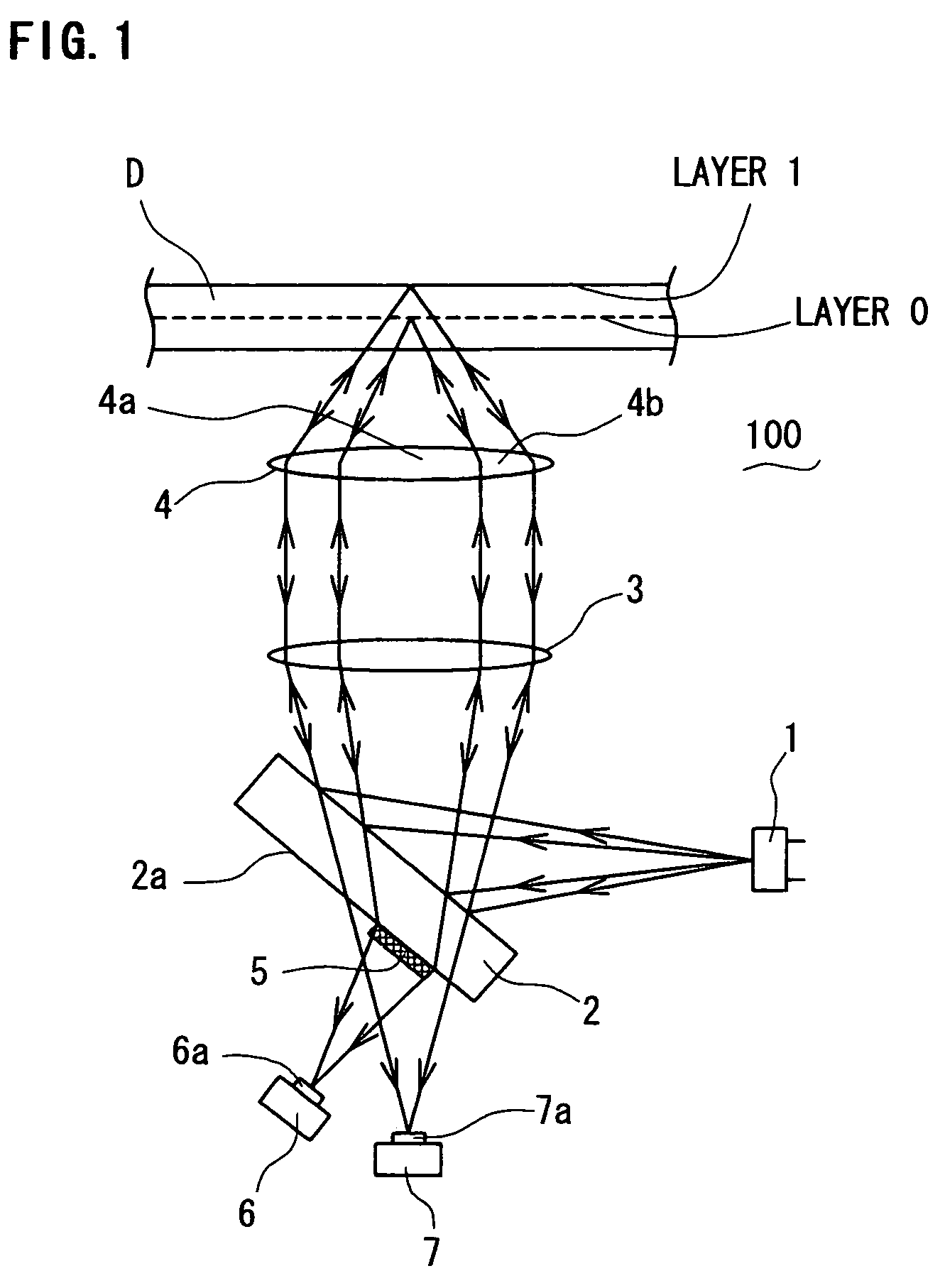
[0025]An optical pickup device according to an embodiment of the present invention is described with reference to the drawings. FIG. 1 shows a structure of the optical pickup device. The optical pickup device 100 is a device mounted in an optical disk recording and playback device and used to read and write data to an optical disk D. The device comprises a laser diode (laser light source) 1 for emitting a laser beam, a half mirror 2 for directing the laser beam emitted from the laser diode 1 toward the optical disk D and transmitting the laser beam reflected by the recording surface of the optical disk D, a collimator lens 3 for converting the laser beam reflected by the half mirror 2 into parallel light, an object lens 4 for condensing the laser beam that has been converted to parallel light by the collimator lens 3 onto the recording surface of the optical disk D, a diffraction grating 5 for diffracting a part of the laser beam that is transmitted through the h...

embodiment 2

[0034](Embodiment 2)

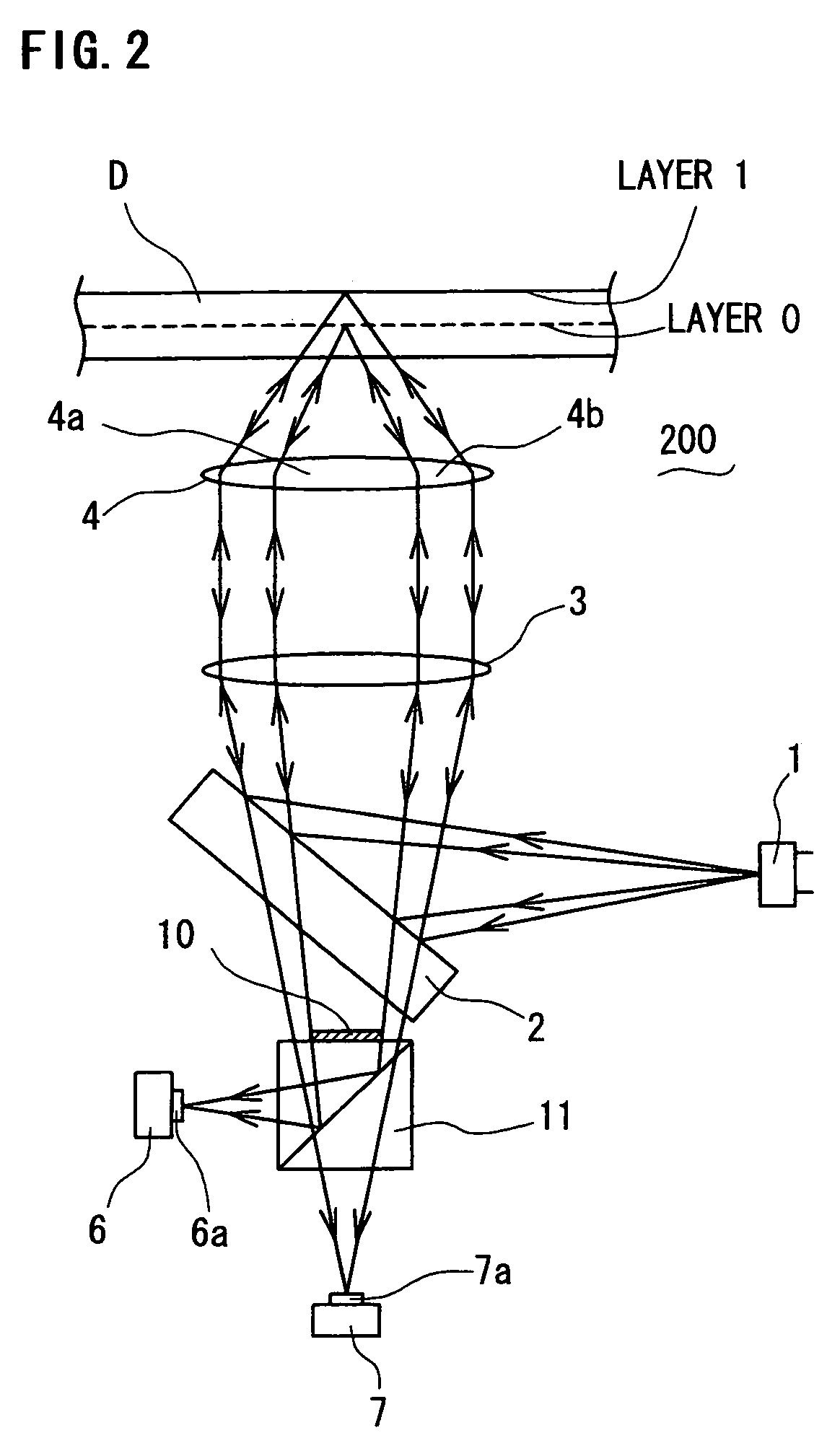
[0035]The optical pickup device according to another embodiment of the present invention is described below with reference to FIG. 2. The optical pickup device 200 comprises a laser diode 1, a half mirror 2, a collimator lens 3, an object lens 4, and photodetectors 6 and 7, and further comprises a half-wave plate 10 for changing the direction of the laser beam reflected by the recording surface of layer 0 by 90°, and a polarized beam splitter 11 for reflecting the laser beam that is transmitted through the half-wave plate 10 in the direction of the photodetector 6 and transmitting the laser beam reflected by the recording surface of layer 1.

[0036]The data writing operation in the optical pickup device 200 constituted as noted above is performed in the same manner as in the optical pickup device 100. The data reading operation in the optical pickup device 200 is described below. The laser beam condensed on the recording surface of layer 0 by the central area 4a of...

embodiment 3

[0037](Embodiment 3)

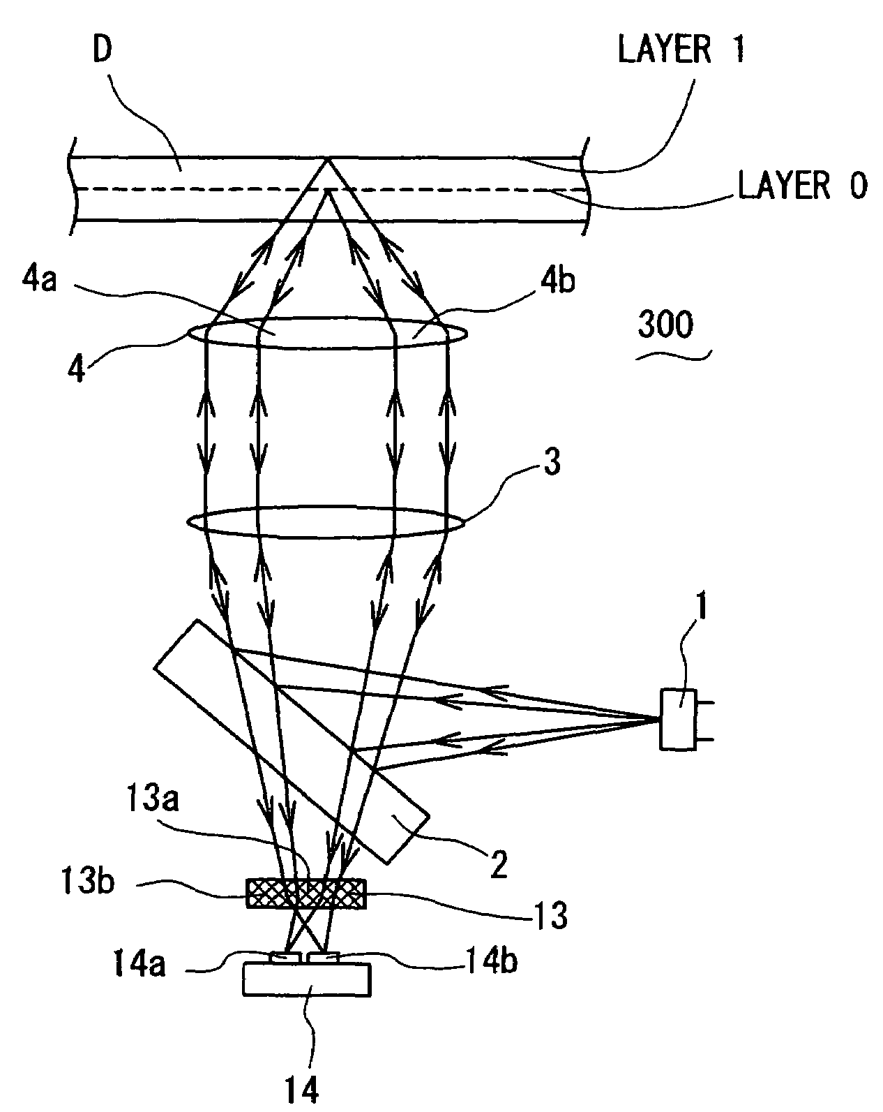
[0038]The optical pickup device according to further another embodiment of the present invention is described below with reference to FIG. 3. The optical pickup device 300 comprises a laser diode 1, a half mirror 2, a collimator lens 3, and an object lens 4, and further comprises a diffraction grating 13 for diffracting the laser beam reflected by layer 0 and the laser beam reflected by layer 1 in different directions, and a photodetector 14 having light-receiving portions 14a and 14b for receiving the laser beams diffracted in different directions by the diffraction grating 13. The diffraction grating 13 has different grating shapes in the central area 13a into which the reflected laser beam is reflected by the layer 0, and in the outside area 13b into which the reflected laser beam is reflected by the layer 1. In the present embodiment, a hologram for condensing the laser beam toward the light-receiving portions 14a and 14b of the photodetector 14 may be used i...


PUM

PropertyMeasurementUnit
refractive indexaaaaaaaaaa
period of timeaaaaaaaaaa
reading speedaaaaaaaaaa

Abstract

There is provided an optical pickup device comprising a laser light source for emitting a laser beam, an object lens for focusing the laser beam onto the recording surfaces of layers 0 and 1 of an optical disk and condensing the laser beam onto the recording surfaces, photodetectors for receiving the laser beam reflected by the optical disk, and a diffraction grating for diffracting a part of the reflected laser beam toward the photodetectors, wherein data can be simultaneously written to layers 0 and 1. The photodetector detects the reflected light from layer 0 after being refracted by the diffraction grating, and detects the reflected light from layer 1 without being refracted, so that the data of layers 0 and 1 can be simultaneously read. Thus, data can be simultaneously read from and written to the recording surfaces of a plurality of layers of an optical disk.

Description

BACKGROUND OF THE INVENTION[0001]1. Field of the Invention[0002]The present invention relates to an optical pickup device for reading or writing information to an optical disk having recording surfaces of a plurality of layers, and to an optical disk playback device provided therewith.[0003]2. Description of the Related Art[0004]In recent years, greater recording capacity for optical disks had been required, and DVD (Digital Versatile Disk) and other optical disks obtained by laminating the recording surfaces of a plurality of layers have therefore come into practical use. In an optical disk recording and playback device for recording and playing back data to and from an optical disk having the recording surfaces of such a plurality of layers, as shown in FIG. 5, while an optical pickup device 500 for reading or writing data to an optical disk D is moved in the focus-adjusting direction as indicated by the arrow, an object lens 4 focuses a laser beam on one of the recording surfaces...

Claims


Application Information

Patent Timeline
Patent Type & Authority Patents(United States)
IPC IPC(8): G11B7/00G11B7/005G11B7/0045G11B7/135G11B7/1353G11B7/1365G11B7/14
CPCG11B7/1353G11B7/14G11B7/1365G11B2007/0013
Inventor MIYATAKE, KENSHOU
Owner FUNAI ELECTRIC CO LTD
Why Eureka
Try Eureka