Low cost wind tunnel for supersonic and hypersonic aerothermal testing

a supersonic and hypersonic technology, applied in the direction of measurement devices, structural/machine measurement, instruments, etc., can solve the problem that conventional technology is limited to testing, and achieve the effect of accurate aerothermal testing, easy control, and reduced mass flow ra

Inactive Publication Date: 2008-07-22
THE UNITED STATES OF AMERICA AS REPRESENTED BY THE SECRETARY OF THE NAVY
View PDF2 Cites 54 Cited by
  • Summary
  • Abstract
  • Description
  • Claims
  • Application Information

AI Technical Summary

Benefits of technology

[0011]The present invention solves the problem of having to accelerate a hot gas to supersonic or hypersonic speeds to accurately perform aerothermal testing upon a test object under conditions simulating supersonic or hypersonic flight. The present invention permits a subsonic condition to be utilized to match the shear and heat flux that would occur during a supersonic or hypersonic flight trajectory. The Mach number, pressure, and temperature in the wind tunnel are all easily controllable to match a predetermined heat flux and shear.
[0012]The invention permits larger items to be tested in a given wind tunnel because lower mass flow rates are required. Utilizing the present invention, the mass flow rates required to test the object are greatly reduced as compared to a hypersonic wind tunnel. For an equivalent mass flow rate, the present invention affords the use of a larger test section allowing for testing of larger objects than would otherwise be the case.
[0013]A feature of the present invention is that the static pressure surrounding the test article need not be reduced to simulate high altitude, low-pressure flight. Rather, the operating pressure may be chosen initially and then equivalent subsonic conditions determined to match that pressure. It is beneficial to be able to choose the operating pressure because as the operating pressure is increased, the Mach number required for the equivalent subsonic condition decreases.
[0014]The invention additionally permits the Mach number in the test section to be varied during operation of the wind tunnel. Conventional technology typically is limited to testing at a single condition. An accurate simulation of a complete trajectory requires conditions that change in time to match those experienced in flight. The present invention allows the heat flux and shear to be varied in time to accurately simulate the complete trajectory of a test article.

Problems solved by technology

Conventional technology typically is limited to testing at a single condition.

Method used


Image

  • Low cost wind tunnel for supersonic and hypersonic aerothermal testing
  • Low cost wind tunnel for supersonic and hypersonic aerothermal testing
  • Low cost wind tunnel for supersonic and hypersonic aerothermal testing

Examples


Embodiment Construction

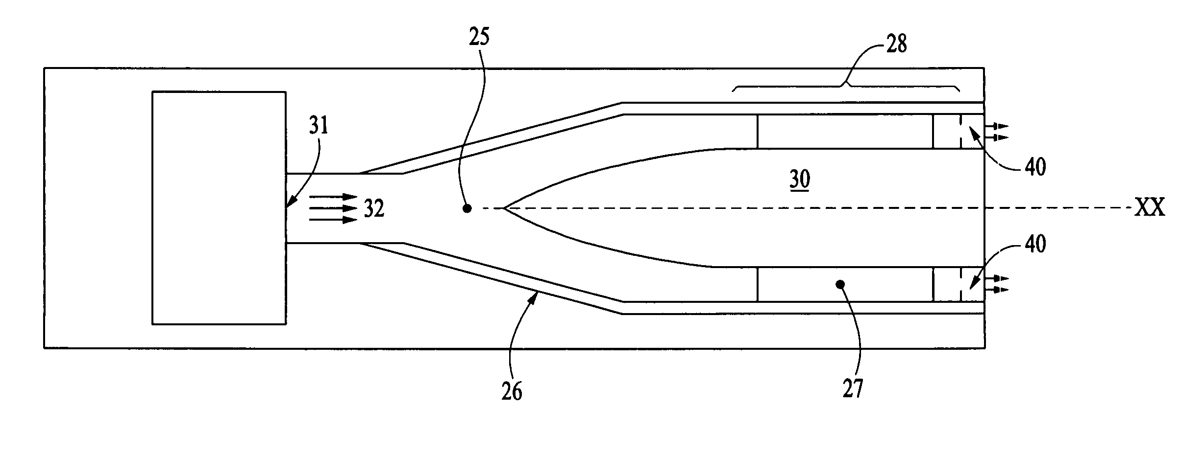
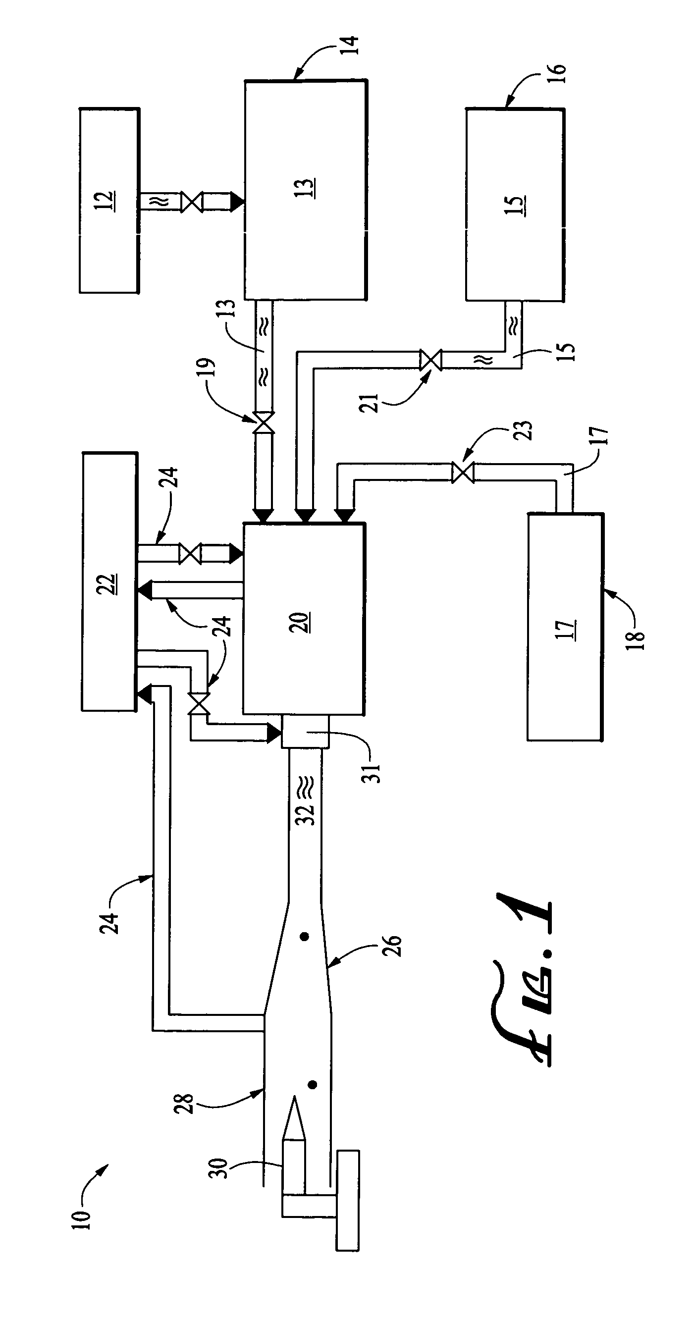
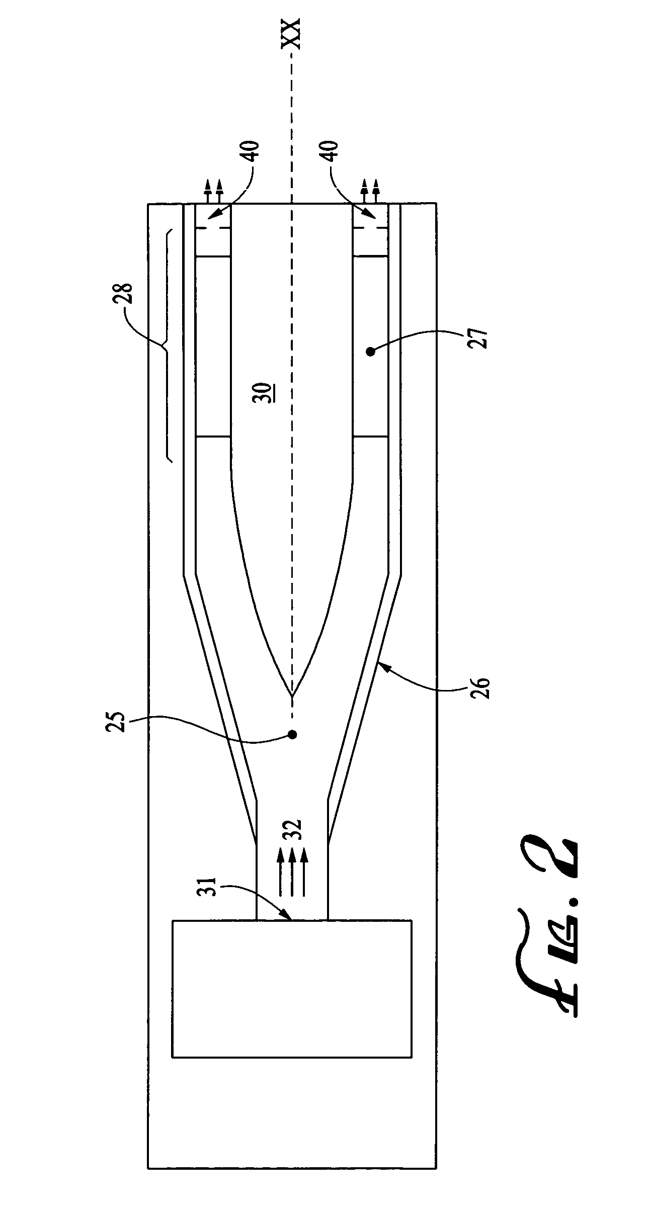
[0021]Referring to FIGS. 1 & 2, subsonic wind tunnel 10 is described. Air compressor 12 provides compressed air 13 to compressed air storage tank 14. Compressed air storage tank 14 delivers compressed air 13 to sudden expansion air heater 20 where compressed air 13 is mixed with fuel 15 such as propane supplied by fuel storage tank 16. It will be understood that other conventional sources of compressed air, such as fans, turbines and the like may also be used to supply compressed air. Hydrogen 17 is optionally added to the fuel air mixture to enhance ignition of the fuel air mixture. Alternatively, compressed air 13 is heated using other conventional methods such as a vitiated air heater, arc jet, or pebble bed heater to produce heated gas 32. Pressurized water supply 22 cools wind tunnel 10 and helps regulate the temperature of the wind tunnel components. Heated gas 32 flows through flow straightener 31 and into diffuser lumen 25 of subsonic diffuser 26. Subsonic diffuser 26 is cou...


PUM


Abstract

The invention disclosed herein provides a subsonic wind tunnel capable for accurately maintaining a desired Mach number, pressure and temperature for use in aerothermal testing of materials. The invention allows the Mach number to be precisely controlled in the test section of the wind tunnel by employing a restricted outlet acting as a sonic throat for the wind tunnel. In the preferred embodiment, the restricted outlet is constructed to be variable in cross sectional area allowing a range of Mach numbers to be tested. The variable outlet is varied during the operation of the wind tunnel so that an actual trajectory with changing Mach numbers, pressure, and temperature is simulated.

Description

STATEMENT REGARDING FEDERALLY SPONSORED RESEARCH OR DEVELOPMENT[0001]The invention described herein may be manufactured and used by or for the government of the United States of America for governmental purposes without the payment of any royalties thereon or therefore.BACKGROUND OF THE INVENTION[0002]1. Field of the Invention[0003]The present invention relates to a wind tunnel testing apparatus and methods for use in aerothermal testing, and more particularly to such materials and methods utilizing a low velocity subsonic flow with shear and heat flux conditions equivalent to a hypersonic or supersonic flight path of a test object.[0004]2. Description of the Prior Art[0005]The use of wind tunnels for simulating flight conditions is a common practice in the aerospace industry. Utilizing wind tunnels, objects are subjected to carefully controlled environmental conditions and monitored to determine how the object behaves. All wind tunnels operate under the same basic principle. A gas ...

Claims


Application Information

Patent Timeline
Patent Type & Authority Patents(United States)
IPC IPC(8): G01M9/00
CPCG01M9/04
Inventor SCHULTZ, RONALDJAUL, WARREN KENDRICK
Owner THE UNITED STATES OF AMERICA AS REPRESENTED BY THE SECRETARY OF THE NAVY
Why Eureka
Try Eureka