DC offset correction for direct-conversion receiver

a direct-conversion receiver and offset correction technology, applied in the field of radio frequency receivers, can solve the problems of direct-conversion receivers with a number, leakage, distortion and direct current offset, and the most serious dc offs

Inactive Publication Date: 2008-07-22
SYNAPTICS INC
View PDF10 Cites 25 Cited by
  • Summary
  • Abstract
  • Description
  • Claims
  • Application Information

AI Technical Summary

Problems solved by technology

Unfortunately, direct-conversion receivers have a number of problems that include spurious LO leakage, distortion and direct current (“DC”) offset.
Of these problems, typically the DC offset is the most serious because the DC offset may appear in the middle of the down-converted signal spectrum and may be larger than the received signal itself.
Additionally, the DC offset is typically larger than the thermal and flicker noise.
The DC offset is unavoidable because it is caused by the transistor level amplifiers and filters due to mismatches in the signal path and spurious LO leakage.
This LO leakage may result in a large DC offset because of self-mixing.
This may drive any active components within the baseband section out of their dynamic range causing distortion to the desired baseband signals.
As a result, it is typically difficult to achieve high performance in integrated direct-conversion receivers because of the effects of the DC offset problem.
The saturated circuitry may resultantly generate harmonics and inter-modulation tones that would unfortunately increase the implementation loss of the satellite receiver.
Unfortunately, large capacitors may lower the response time of the direct-conversion receiver.
Additionally, large capacitors in a direct-conversion...

Method used


Image

  • DC offset correction for direct-conversion receiver
  • DC offset correction for direct-conversion receiver
  • DC offset correction for direct-conversion receiver

Examples


Embodiment Construction

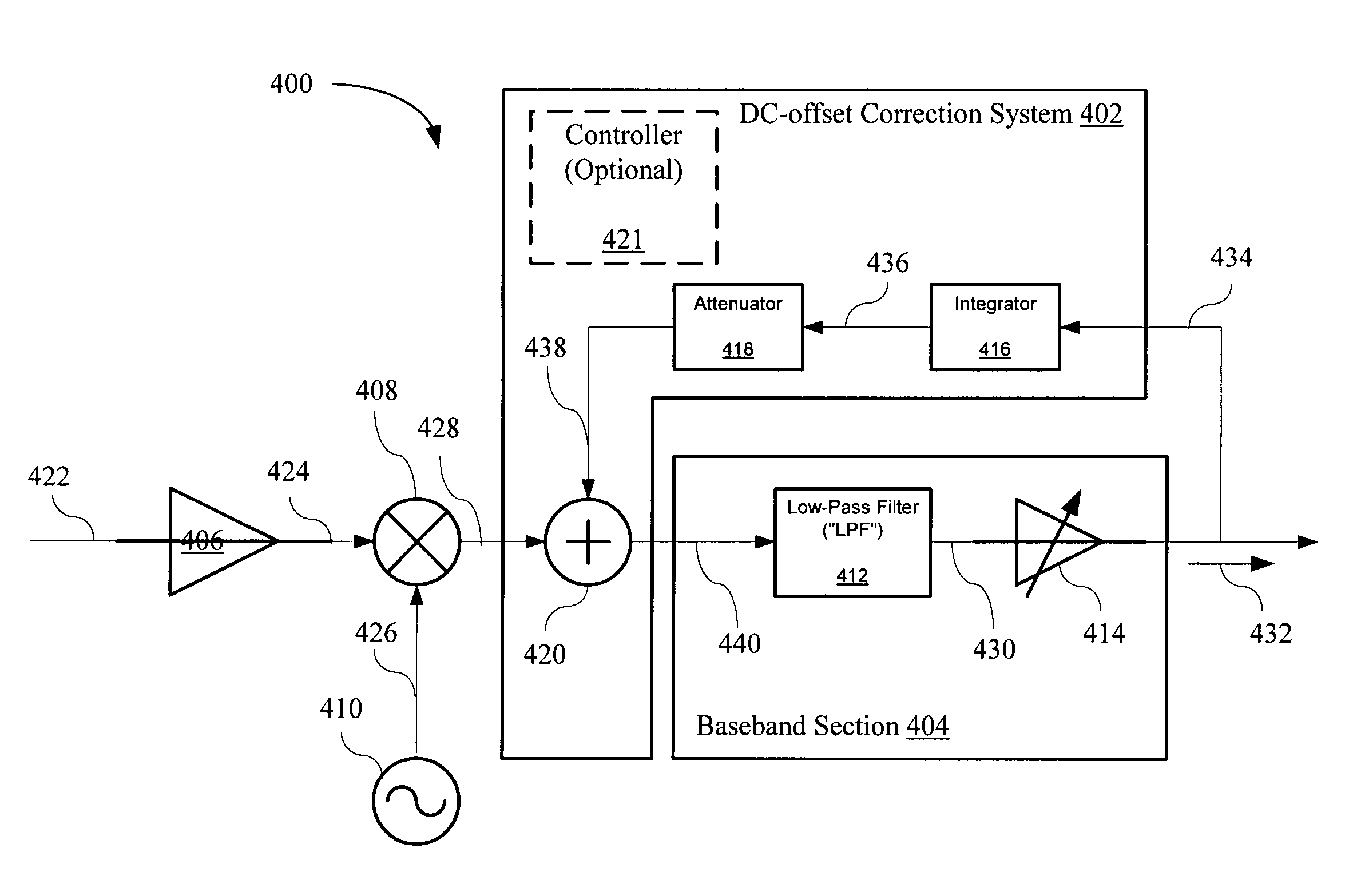
[0034]This invention discloses a direct-current (“DC”) offset correction system (referred to herein as a “DC-offset Correction System”) that corrects for the DC offset present in direct-conversion receivers. Generally, the DC-offset Correct System utilizes an improved DC feedback correction servo-loop that applies an attenuation coefficient in the feedback path.

[0035]In FIG. 4, an example implementation of a direct-conversion receiver 400 utilizing a DC-offset Correction System 402 is shown. The direct-conversion receiver 400 may include the DC-offset Correction System 402 and a baseband section 404, LNA 406, mixer 408, and LO 410. The baseband section 404 may include a LPF 412 and VGA-LNA 414 and the DC-offset Correction System 402 may include an integrator 416, attenuator 418, combiner 420 and optional controller 421. The DC-offset Correction System 402 is a DC feedback correction servo-loop capable of producing an attenuation coefficient kfb within the DC feedback correction serv...


PUM


Abstract

A DC offset correction system for a direct-conversion receiver is disclosed that may include a DC feedback correction servo-loop in signal communication with a baseband section, where the DC feedback correction servo-loop is coupled to both the input and output of the baseband section and an attenuator within the DC feedback correction servo-loop.

Description

BACKGROUND OF THE INVENTION[0001]1. Field of the Invention[0002]This invention relates generally to radio frequency (“RF”) receivers and in particular to direct-conversion receivers with direct current (“DC”) offset correction.[0003]2. Related Art[0004]In today's society, telecommunications systems are evolving at a rapid pace in response to the demands of society for more wireless communication systems, higher performance entertainment medium transmissions (via airwave, wired or satellite based) and broadband access whether wired or wireless. This evolution typically involves improving the performance of the communication system receivers or transceivers (i.e., which includes a receiver) while at the same time simplifying their manufacture.[0005]Integrated circuit (“IC”) technology has lead to numerous advances in receiver technology through both transistor scaling and layout by increasing the density of active circuits that may be integrated into a receiver. Additionally, there ar...

Claims


Application Information

Patent Timeline
IPC IPC(8): H04B1/00H03D3/00H04B1/30H04L25/06H04L27/36
CPCH03D3/008H04L27/362H04L25/06H04B1/30
Inventor GAO, WEINAN
Owner SYNAPTICS INC
Why Eureka
Try Eureka