Circuit and method for receiving and mixing radio frequencies in a direct conversion receiver

a receiver and circuit technology, applied in the field of direct conversion receivers and circuits for receiving and mixing radio frequencies, can solve the problems of secondary intermodulation distortion, dcr has some problems, secondary intermodulation distortion generated by the mixer, etc., and achieve the effect of improving the linearity of the mixing circuit and the quality of the receiving circui

Inactive Publication Date: 2006-10-10
SAMSUNG ELECTRONICS CO LTD
View PDF10 Cites 32 Cited by
  • Summary
  • Abstract
  • Description
  • Claims
  • Application Information

AI Technical Summary

Benefits of technology

[0033]The present invention renders the secondary intermodulation distortion IMD2 reduced by changing input structure of the mixing circuit that rece...

Problems solved by technology

However, the DCR has some problems.
One of the problems is a secondary intermodulation distortion generated by the mixer.
The secondary intermodulation distortion is caused by the mixer having a nonlinear active device.
Additionally, because the DCR shif...

Method used


Image

  • Circuit and method for receiving and mixing radio frequencies in a direct conversion receiver
  • Circuit and method for receiving and mixing radio frequencies in a direct conversion receiver
  • Circuit and method for receiving and mixing radio frequencies in a direct conversion receiver

Examples


embodiment 1

[0044

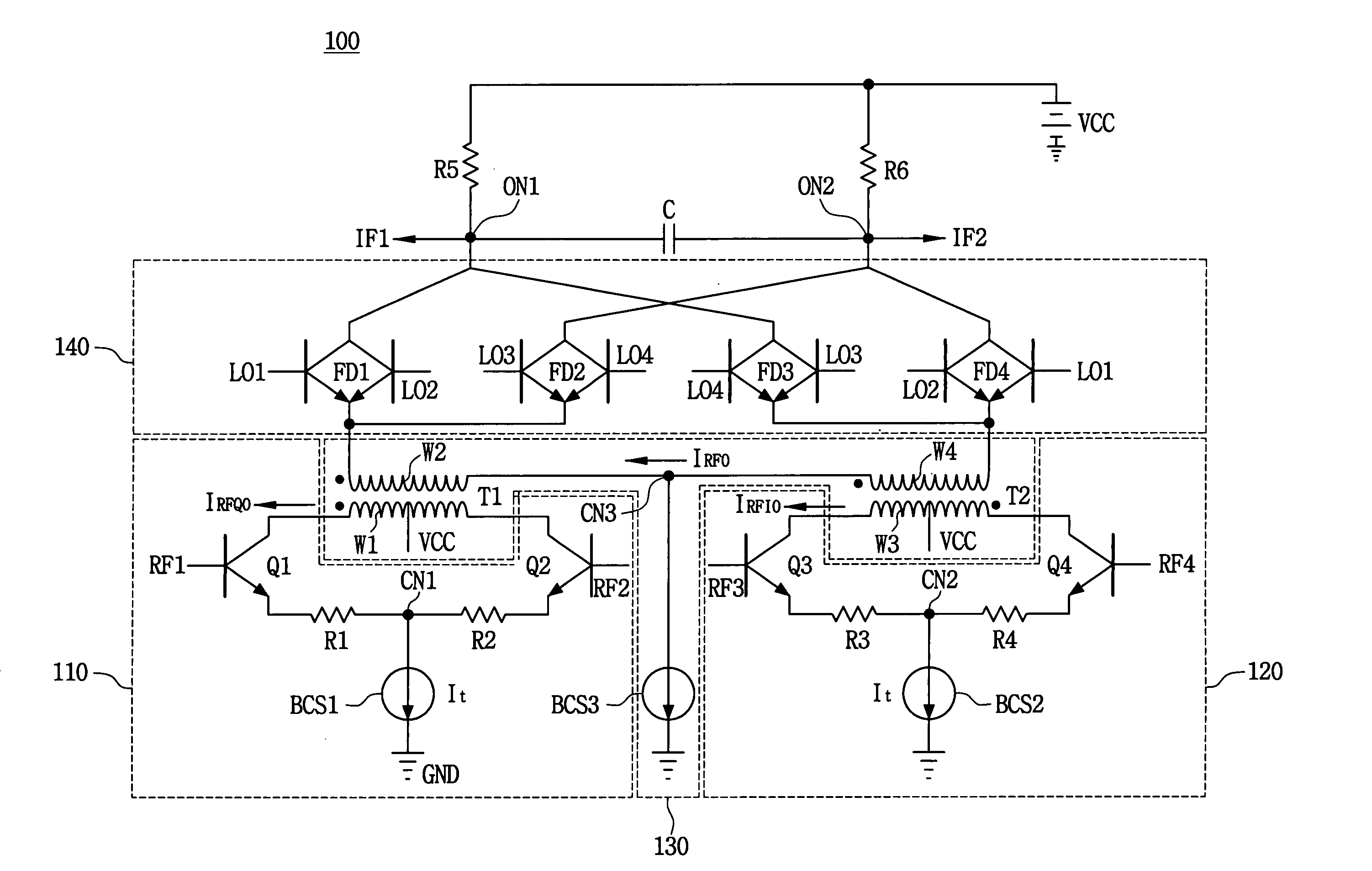
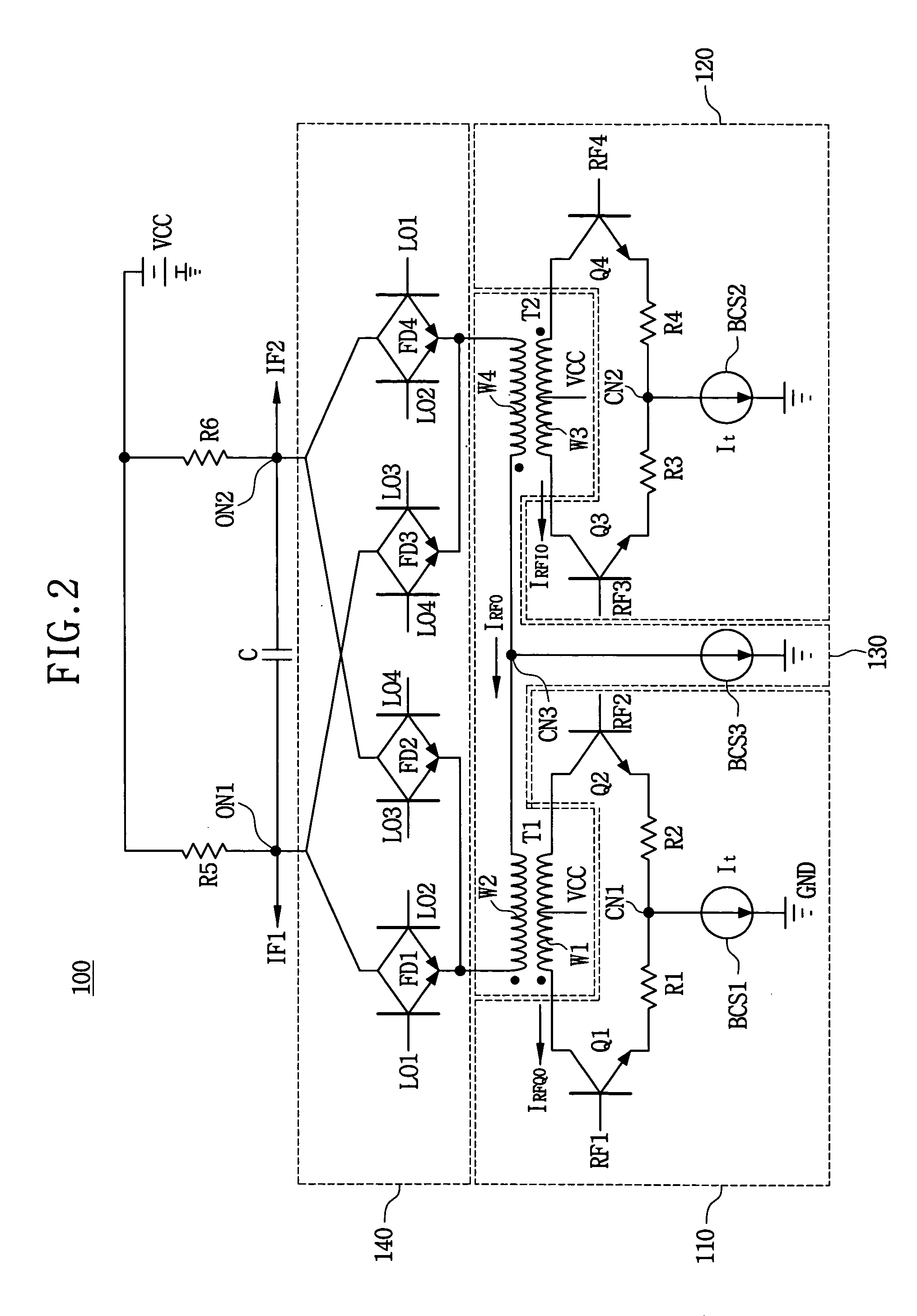
[0045]FIG. 2 is a circuit diagram of a harmonic rejection mixing circuit according to a first embodiment of the present invention.

[0046]Referring to FIG. 2, a frequency mixing circuit 100 comprises a first differential amplifier 110, a second differential amplifier 120, a subtracter 130 and a mixer 140.

[0047]The first differential amplifier 110 has a pair of an emitter coupled transistors Q1 and Q2 that are emitter coupled at first common node CN1. The first transistor Q1 has a base receiving a first input signal RF1 and the second transistor Q2 has a base receiving a second input signal RF2. The first input signal RF1 and the second input signal RF2 are 180° out of phase with respect to each other, and become a first pair input signals. The first differential amplifier 110 generates a first amplified signal IRFQ0 by amplifying the first pair input signals RF1 and RF2. A first bias current source BCS1 is connected between the first common node CN1 (of the emitter coupled transi...

embodiment 2

[0062

[0063]FIG. 3 is a circuit diagram of a harmonic rejection mixing circuit according to a second embodiment of the present invention.

[0064]A frequency mixing circuit shown in FIG. 3 has the same configuration as the first embodiment of the frequency mixing circuit as shown in FIG. 2, except for the mixer 240. Therefore, in FIG. 3, the same reference numerals denote the same elements in FIG. 2, and thus the detailed description of the same elements will be omitted.

[0065]Referring to FIG. 3, the mixer 240 has a double balanced mixing circuit including a Gilbert cell circuit. Thus, the frequency of drive signals L01 and L02 is the same as the frequency of input signals RF1, RF2, RF3 and RF4.

[0066]A first pair of emitter coupled transistors Q5 and Q6 has emitters commonly connected to each other and connected to one terminal of the second winding W2. The collector of one of the first pair of emitter coupled transistors Q5 and Q6 is connected to the first output node ON1, and the coll...

embodiment 3

[0068

[0069]FIG. 4 is a circuit diagram of a harmonic rejection mixing circuit according to a third embodiment of the present invention.

[0070]Referring to FIG. 4, a frequency mixing circuit 400 has a differential amplifier 410. The differential amplifier 410 amplifies a first pair of input signals RF1 and RF2 in order to output a first current signal IRF1 and a second current signal IRF2. =A current to flow at a first node N1 into transistor Q13 is the first current signal IRF1 and a current to flow at a second node N2 into transistor Q14 is the second current signal IRF2. The differential amplifier 410 has a pair of emitter coupled transistors Q13 and Q14 and a bias current source BCS7. Transistor Q13 has a collector connected to the first node N1, a base receiving the first input signal RF1 having 0° phase, and an emitter connected a common node CN4 via a regeneration resistor R7. Transistor Q14 has a collector connected to the second node N2, a base receiving the second input sign...


PUM


Abstract

A frequency mixing circuit and a frequency mixing method. The frequency mixing circuit includes first and second differential amplifiers, a subtracter and a mixer. The first differential amplifier amplifies a first pair of input signals having a first frequency to generate a first differential signal. The second differential amplifier amplifies a second pair of input signals having the first frequency orthogonal to the first pair input signals to generate a second differential signal. The subtracter subtracts the second differential signal from the first differential signal. The mixer mixes the subtracted signal with a first and second pairs of drive signals having a second frequency orthogonal to each other, in a sub-harmonic double balanced mixing mode, so that the mixer generates a pair of output signals orthogonal to each other without secondary harmonics.

Description

BACKGROUND OF THE INVENTION[0001]1. Field of the Invention[0002]The present invention relates to direct conversion receivers and circuits and methods for receiving and mixing radio frequencies, and more particularly to a circuit and a method that can diminish a secondary-order inter modulation distortion at a direct conversion receiver.[0003]2. Description of the Related Art[0004]Generally, the direct conversion receiver or a homodyne receiver provides advantages compared to a superheterodyne receiver.[0005]FIG. 1 is a radio frequency receiving circuit diagram of a conventional direct conversion receiver (DCR).[0006]Referring to FIG. 1, the direct conversion receiver transforms an input signal into an inphase signal and a quadrature signal having a baseband frequency without transforming the input signal into a signal having an intermediate frequency (IF).[0007]A radio frequency (RF) signal received by an antenna 10 is inputted to a low noise amplifier 12, and then an output signal ...

Claims


Application Information

Patent Timeline
IPC IPC(8): H04B1/26G01V3/02H03D7/00H03D7/14H03D7/16H04B1/30
CPCH03D7/1433H03D7/165H04B1/30H03D7/1441H03D7/1458H03D7/1475H03D7/1491H03D2200/0043H03D2200/0047H03D2200/009H03D7/00
Inventor KIM, YOUNG-JINHWANG, IN-CHUL
Owner SAMSUNG ELECTRONICS CO LTD
Why Eureka
Try Eureka