
Method and system for advanced process control including tool dependent machine constants

a technology of advanced process control and tool dependent machine constant, which is applied in the direction of adaptive control, semiconductor/solid-state device testing/measurement, instruments, etc., can solve the problems of loss of the complete integrated circuit, total product cost, extreme cost-intensive, etc., and achieve the effect of enhancing controller performance and improving control efficiency

Active Publication Date: 2008-07-22
ADVANCED MICRO DEVICES INC
View PDF7 Cites 24 Cited by
  • Summary
  • Abstract
  • Description
  • Claims
  • Application Information

AI Technical Summary

Benefits of technology

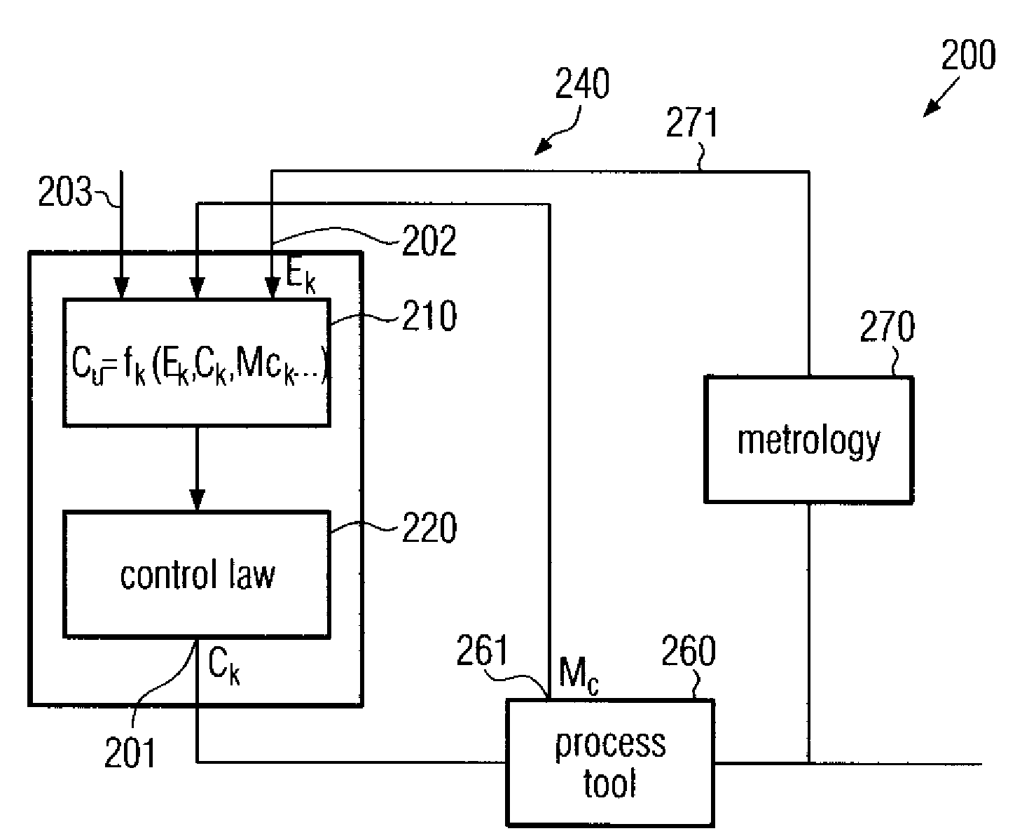
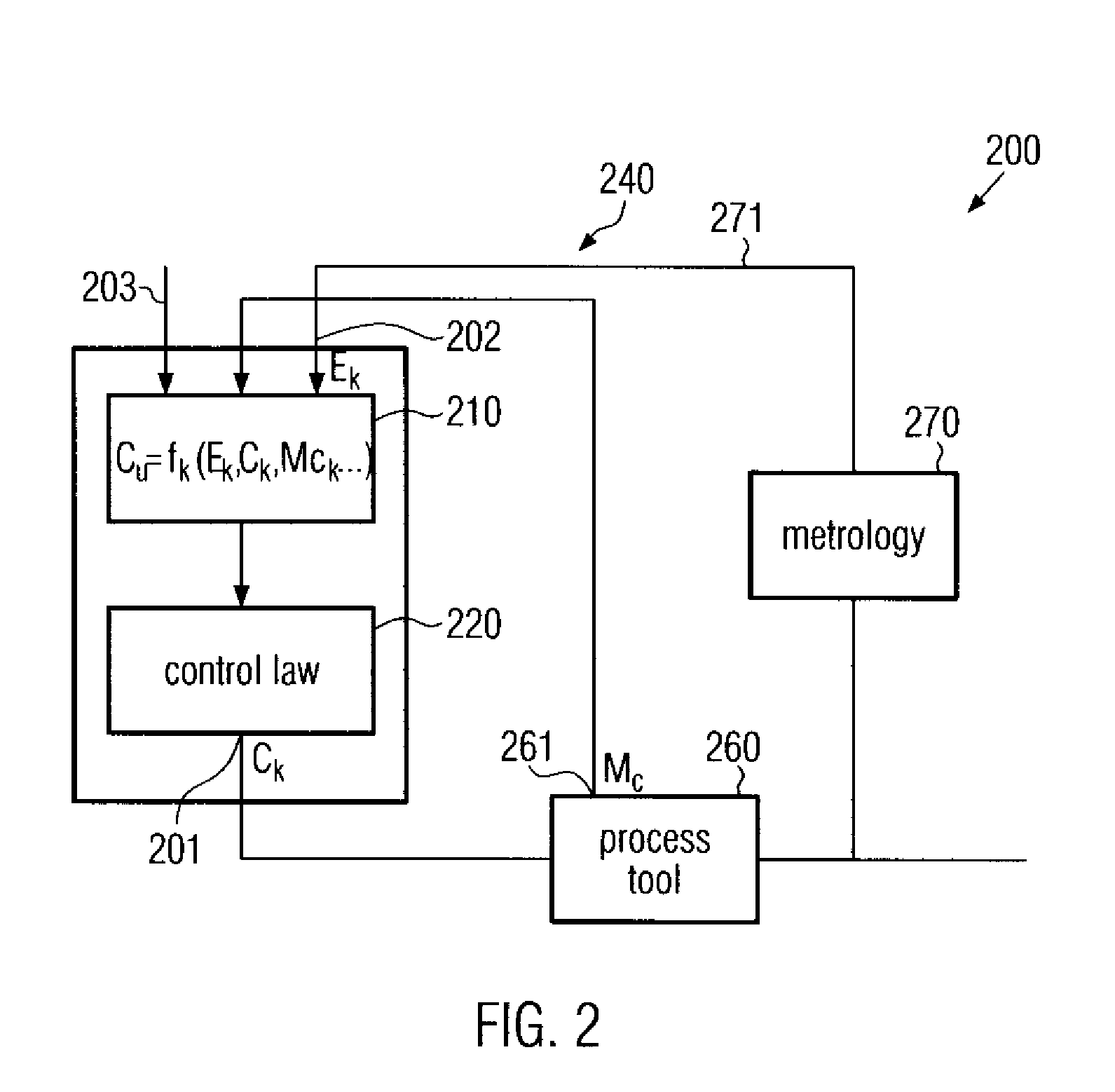
[0015]Generally, the present invention is directed to a technique that provides enhanced control efficiency for process tools that are operated on the basis of machine constants which have to be verified on a regular basis. For this purpose, the machine constants or any data related thereto may explicitly be included into a model predictive control strategy, thereby significantly enhancing controller performance after a “step disturbance” introduced by updated values of the machine constants.

Problems solved by technology

The latter aspect is especially important, since in modern semiconductor facilities, equipment is required which is extremely cost-intensive and represents the dominant part of the total product costs.
For example, in manufacturing modern integrated circuits, 500 or more individual processes may be necessary to complete the integrated circuit, wherein failure in a single process step may result in a loss of the complete integrated circuit.
This problem is even exacerbated in that the size of substrates, on which a plurality of such integrated circuits are processed, steadily increases, so that failure in a single process step may entail the loss of a large number of products.
A corresponding process control, however, is not practical, since measuring the effects of certain processes may require relatively long measurement times, frequently ex situ, or may even necessitate the destruction of the sample.
Moreover, immense effort, in terms of time and equipment, would have to be made on the metrology side to provide the required measurement results.
Nevertheless, in total, a large number of dummy substrates or pilot substrates may be necessary to adjust process parameters of respective process tools, wherein tolerable parameter drifts during the process have to be taken into consideration when designing a process sequence, since such parameter drifts may remain undetected over a long time period or may not efficiently be compensated for by SPC techniques.
On the other hand, lithography is a highly cost-intensive process and undue reprocessing of out-of-control substrates may substantially contribute to overall production costs.
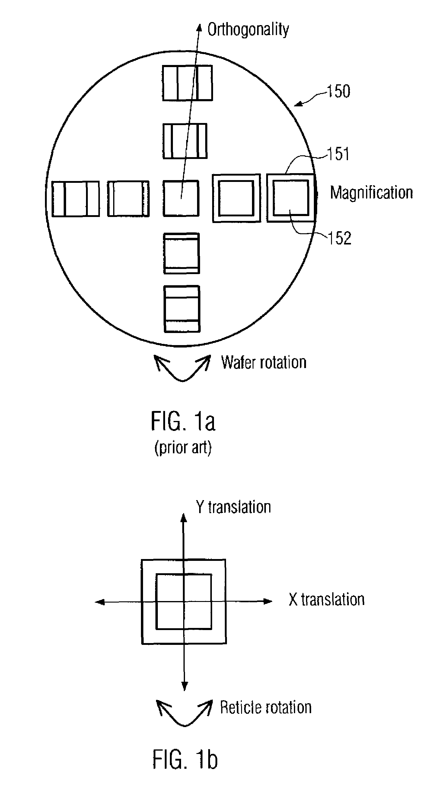
One problem, in addition to the appropriate imaging of a mask pattern into a photoresist layer, is the overlay accuracy of lithography processes performed in different device layers.
Thus, irrespective of the control scheme used, a reduced controller performance may be obtained owing to the changes of machine constants, since the occurrence of step disturbances, introduced by the updated machine constants which directly affect the set point calibration and thus the controller performance, may result in declined controller performance immediately after the disturbance, while resetting of the controller may result in reduced throughput and compromised controller performance at an initial phase.

Method used


Image

  • Method and system for advanced process control including tool dependent machine constants
  • Method and system for advanced process control including tool dependent machine constants
  • Method and system for advanced process control including tool dependent machine constants

Examples


Embodiment Construction

[0024]Illustrative embodiments of the invention are described below. In the interest of clarity, not all features of an actual implementation are described in this specification. It will of course be appreciated that in the development of any such actual embodiment, numerous implementation-specific decisions must be made to achieve the developers' specific goals, such as compliance with system-related and business-related constraints, which will vary from one implementation to another. Moreover, it will be appreciated that such a development effort might be complex and time-consuming, but would nevertheless be a routine undertaking for those of ordinary skill in the art having the benefit of this disclosure.

[0025]The present invention will now be described with reference to the attached figures. Various structures, systems and devices are schematically depicted in the drawings for purposes of explanation only and so as to not obscure the present invention with details that are well ...


PUM

PropertyMeasurementUnit
currentaaaaaaaaaa
sizeaaaaaaaaaa
timeaaaaaaaaaa

Abstract

A controller and a method of controlling a process tool is provided, in which machine constants used for calibrating manipulated variables of the control algorithm are explicitly introduced into the process model, thereby providing an enhanced controller behavior immediately after the introduction of new measurement values of the machine constants.

Description

BACKGROUND OF THE INVENTION[0001]1. Field of the Invention[0002]The present invention relates to the field of fabricating semiconductor devices, and, in particular, to advanced process control (APC) techniques for manufacturing processes, wherein an improved process control quality is achieved by adjusting process parameters in a predictive manner on the basis of a process model and measurement data.[0003]2. Description of the Related Art[0004]Today's global market forces manufacturers of mass products to offer high quality products at a low price. It is thus important to improve yield and process efficiency to minimize production costs. This holds especially true in the field of semiconductor fabrication, since here it is essential to combine cutting edge technology with mass production techniques. It is, therefore, the goal of semiconductor manufacturers to reduce the consumption of raw materials and consumables while at the same time improve product quality and process tool utili...

Claims


Application Information

Patent Timeline
Patent Type & Authority Patents(United States)
IPC IPC(8): G06F19/00
CPCG05B13/048
Inventor SCHULZE, UWEKNAPPE, UWE
Owner ADVANCED MICRO DEVICES INC
Learn More