Method for improving design window

a technology of design window and via, applied in the direction of semiconductor/solid-state device details, instruments, photomechanical equipment, etc., can solve the problems of self-heating effects, affecting the performance and reliability of the fabricated circuit, and both reliability and performance problems in the integrated circuit, so as to reduce the optical proximity effect and increase the spacing between the vias

Inactive Publication Date: 2008-07-22
TAIWAN SEMICON MFG CO LTD
View PDF18 Cites 12 Cited by
  • Summary
  • Abstract
  • Description
  • Claims
  • Application Information

AI Technical Summary

Benefits of technology

[0013]In accordance with yet another aspect of the present invention, a semiconductor structure includes a first via and a second via having a first spacing. At least one of the first and second vias has a length and a width substantially less than the length. By forming rectangular vias, the spacing between the vias is increased, hence reducing optical proximity effects.

Problems solved by technology

The quality of the interconnection structure drastically affects the performance and reliability of the fabricated circuit.
The interconnection structure of FIG. 1 experiences several problems.
Such small vias can cause both reliability and performance problems in an integrated circuit.
Reliability problems are caused by high concentrations of current or current crowding effects, which in turn causes self-heating effects, and hence electro-migration.
As a result, voids, open circuits and other reliability problems such as high RC delay, which is caused by high contact resistance, arise.
Similar problems also occur to contacts, contacts being a term typically used to describe a via between a first metal layer and an underlying active or passive component.
Although the addition of the redundant vias reduces the probability of open circuit and / or high RC delay, the distance between the vias decreases.
Due to the close proximity of the vias and other conductive features in the integrated circuit, it is difficult to move vias away from each other without violating design rules.

Method used


Image

  • Method for improving design window
  • Method for improving design window
  • Method for improving design window

Examples


Embodiment Construction

[0024]The making and using of the presently preferred embodiments are discussed in detail below. It should be appreciated, however, that the present invention provides many applicable inventive concepts that can be embodied in a wide variety of specific contexts. The specific embodiments discussed are merely illustrative of specific ways to make and use the invention, and do not limit the scope of the invention.

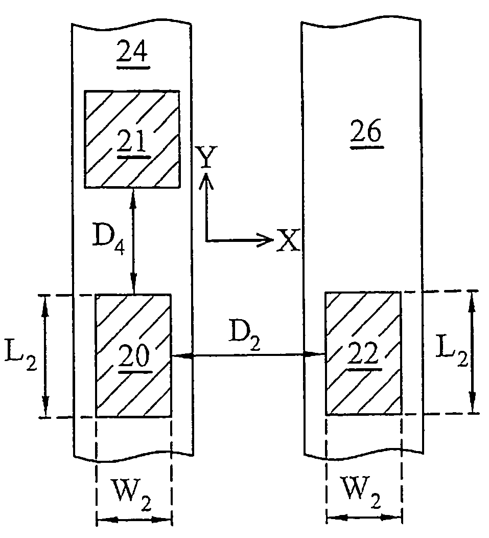
[0025]A novel method for forming photo masks and for forming vertical conductive features is illustrated. The variations of the preferred embodiments are discussed. Throughout the various views and illustrative embodiments of the present invention, like reference numbers are used to designate like elements. For simplicity purposes, the subsequently discussions focus on vias and their formation method. However, the same concepts equally apply to other vertical conductive features, such as contacts. By improving spacing between vertical conductive features, design windows are i...


PUM

PropertyMeasurementUnit
wavelengthaaaaaaaaaa
wavelengthsaaaaaaaaaa

Abstract

A method of forming photo masks having rectangular patterns and a method for forming a semiconductor structure using the photo masks is provided. The method for forming the photo masks includes determining a minimum spacing and identifying vertical conductive feature patterns having a spacing less than the minimum spacing value. The method further includes determining a first direction to expand and a second direction to shrink, and checking against design rules to see if the design rules are violated for each of the vertical conductive feature patterns identified. If designed rules are not violated, the identified vertical conductive feature pattern is replaced with a revised vertical conductive feature pattern having a rectangular shape. The photo masks are then formed. The semiconductor structure can be formed using the photo masks.

Description

[0001]This application claims priority to provisional application Ser. No. 60 / 655,540, filed Feb. 23, 2005, entitled “Method & Improvement of Design Window by Using CAD Utility,” which application is incorporated herein by reference.TECHNICAL FIELD[0002]This invention relates generally to semiconductor integrated circuit fabrication processes, and more particularly to the formation of vias and contacts.BACKGROUND[0003]Modern integrated circuits are made up of literally millions of active devices such as transistors and capacitors. These devices are initially isolated from one another but are later interconnected together to form functional circuits. Typical interconnection structures include lateral interconnections, such as metal lines (wirings), and vertical interconnections, such as vias and contacts. The quality of the interconnection structure drastically affects the performance and reliability of the fabricated circuit. Interconnections are increasingly determining the limits ...

Claims


Application Information

Patent Timeline
Patent Type & Authority Patents(United States)
IPC IPC(8): G06F17/50G03F1/00G06F19/00G21K5/00
CPCG03F1/144G03F1/36H01L21/76816H01L21/76807H01L21/31144H01L2924/0002H01L2924/00H01L23/481
Inventor CHUANG, HARRYTHEI, KONG-BENGYAO, CHIH-TSUNGLIU, HENG-KAICHIU, MING-JERCHEN, CHIEN-WEN
Owner TAIWAN SEMICON MFG CO LTD
Why Eureka
Try Eureka