Method for producing packaging laminated material

a technology of laminated materials and packaging, which is applied in the direction of packaging goods, flexible containers, bottling operations, etc., can solve the problems of affecting the quality of packaging materials, affecting the appearance of packaging materials, so as to achieve the effect of preventing permeation/moistening and high speed

Inactive Publication Date: 2008-07-29
TETRA LAVAL HLDG & FINANCE SA
View PDF9 Cites 1 Cited by
  • Summary
  • Abstract
  • Description
  • Claims
  • Application Information

AI Technical Summary

Benefits of technology

[0009]The method allows a sealing zone and vicinity thereof to be formed so as to have an antibacterial atmosphere or formed with an antibacterial material. Even for different packaging systems of aseptic packaging and chilled packaging, parts of different packaging systems can be diverted or transferred. Thereby efficient running / employment / operation of the whole packaging system are allowed and, further, this contributes to the saving of energy and materials and the reduction of production cost.
[0015]The laminated material in the web-form used for packaging containers according to the invention is in an elongate strip-form (web-form) capable of forming a number of containers and, that enables filling-up and production of packaging containers continuously at a high speed.
[0022]The advantage of this embodiment is that transcription is carried out at the approximately last step of the formation of the container, and packaging and filling can be therefore efficiently performed by a considerably extended choice of the packaged material. Since the silver-based thin film layer is the innermost layer, a heat-sealable material can be directly heated, enabling effective heating and sealing. Further, the silver component of the thin film (metallic silver, silver ion, silver oxide, etc.) discontinuously covers the whole sealing zones by pressure in heat sealing, and allows the sealing zones and vicinity thereof to be formed so as to have an antibacterial atmosphere or formed with an antibacterial material.
[0025]The advantage of this embodiment is that transcription is carried out at the process where it is rapidly laminated in the laminated material manufacturing plant, and the transferring step can be therefore performed efficiently, that is, at a high speed.
[0028]The advantage of this embodiment is that transcription is carried out at the process where it is rapidly laminated in the laminated material manufacturing plant, and transcription process can be therefore performed efficiently, that is, at a high speed. Further, the direct transfer enables omission of the extra intermediate layer, providing an inexpensive and thin packaging material.

Problems solved by technology

When the laminated materials in the web-form used for packaging containers are piled, and the heat-sealable innermost layer is melted to form a zone to be sealed, liquid foodstuffs to be filled and packaged or the like might be left on the sealing zone and vicinity thereof, and the residue is likely to be polluted by bacteria or the like from the outside.

Method used


Image

  • Method for producing packaging laminated material
  • Method for producing packaging laminated material
  • Method for producing packaging laminated material

Examples


embodiment 1

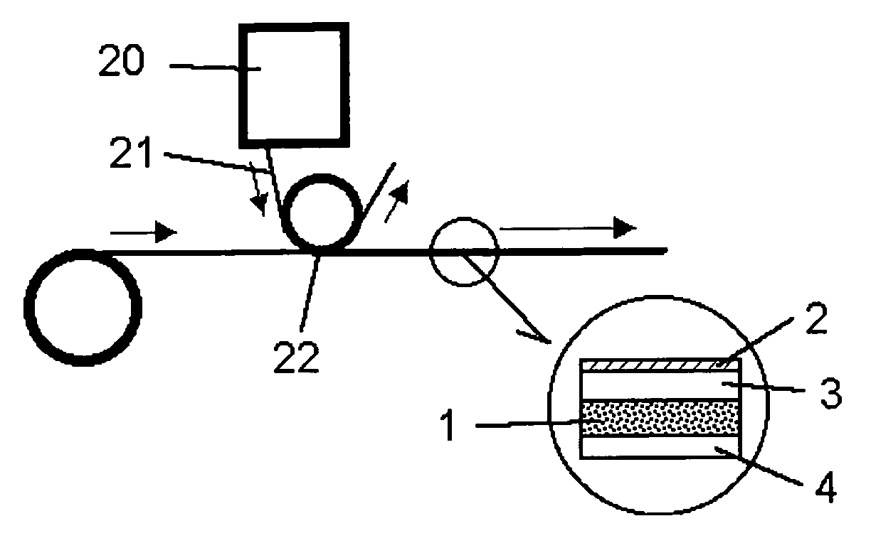
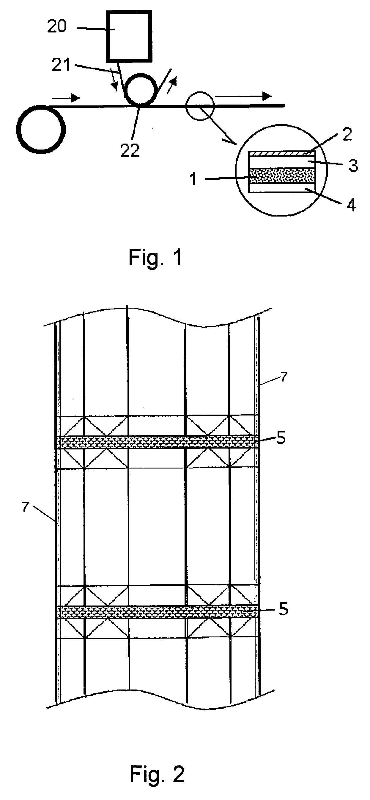
[0038]FIG. 1 is a schematic drawing of process for transferring step of the laminated material in the web-form as an embodiment according to the invention, and an enlarged cross sectional view for a portion of the laminated material. In FIG. 1, the laminated material comprises a support layer 1 made of paper, card board, plastic material or a composite material thereof, a thermoplastic inner layer 3 such as one made of low density polyethylene or linear chain low density polyethylene, a silver-based thin film layer 2 laminated on the inner face of the thermoplastic inner layer 3 at zones where heat-sealing is conducted by high-frequency induction heating so that the heat generated by the induction heating is conducted to the inner layer 3, and an outer layer of thermoplastic material 4 laminated outside.

[0039]The silver-based thin film layer 2 is a layer 2 which the silver-based thin film vapor-deposited on a substrate film 21 is transferred through transferring step by a hot stamp ...

embodiment 2

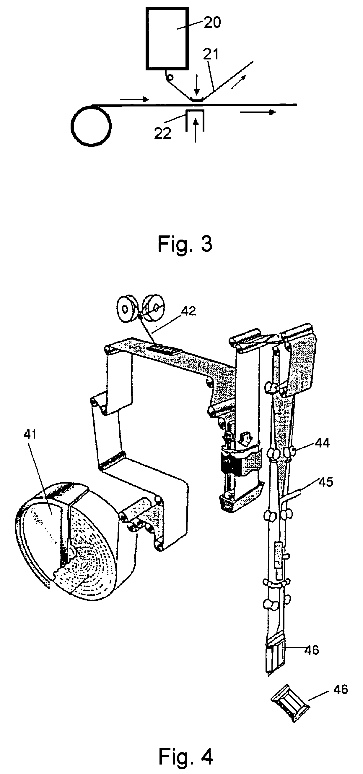
[0054]In the embodiment of claim 2, a transcriber is mounted at the upstream or downstream of the applicator 42, and the strip tape for longitudinal sealing in the packaging and filling machine shown in FIG. 4 is transferred.

[0055]In addition to the container shape in the embodiment described above, the packaging container in the invention includes, for example, a brick-shape (parallelepiped), as well as hexagonal prism, octagonal prism, tetrahedral shape, gable-top containers and the like.

[0056]As has been described above, the following advantageous effect can be obtained according to the invention.

[0057]The sealing zone and vicinity thereof should be formed so as to have an antibacterial atmosphere or formed with an antibacterial material.

[0058]Even for different packaging systems of aseptic packaging and chilled packaging, since a portion of different packaging systems can be diverted or transferred, this enables efficient running / employment / operation of a whole packaging system ...


PUM

PropertyMeasurementUnit
heat-sealableaaaaaaaaaa
timeaaaaaaaaaa
conductiveaaaaaaaaaa

Abstract

A method for producing a laminated material, which comprises providing a raw material roll containing a support layer, drawing out a support layer in a web form from the raw material roll, transferring a silver-based thin film layer on an inner face of the inside of the support layer including a zone to be heat-sealed by the high frequency induction heating for the formation of a container, prior to or after the transferring step, laminating a heat-sealable inner layer on the inside of the support layer, printing the design of the container on the outside of the support layer in a long web form, and forming one or more thermoplastic layers of the same type or different types, at the same time or sequentially, on the outside and the inside of the printed support layer in a web form. The method allows a sealing zone to be formed so as to have an antibacterial atmosphere.

Description

TECHNICAL FIELD[0001]The present invention relates to a method for producing a packaging laminated material.BACKGROUND ART[0002]A laminated material in a web-form used for packaging containers comprising a support layer and a thermoplastic inner layer in which a carbon black conductive layer is laminated between the support layer and the thermoplastic innermost layer at zones to be heat-sealed by high-frequency induction heating for the formation of a container is known (for example, as described in JP-B No. 63-222). In the laminated material, a support layer, a thermoplastic innermost layer and a carbon black conductive layer as an intermediate layer therebetween are constituted.[0003]A packaging machine in which an attaching device for attaching an aluminum foil tape for high-frequency induction heating to a portion of a laminated material in a web-form to be heat-sealed is disposed to conduct high-frequency induction heating the aluminum foil tape by high-frequency coils of a hea...

Claims


Application Information

Patent Timeline
Patent Type & Authority Patents(United States)
IPC IPC(8): B44C1/16B44C1/24B65B51/22B65B61/00B65D33/24B65B61/24B65D33/30B29C53/48B65D65/40B29C65/00B29C65/02B29C65/04B29L22/00B32B15/08B32B27/08B32B37/20B65B51/30
CPCB29C66/83543B29C65/368B29C66/026B29C66/1122B29C66/4312B29C66/72321B32B27/08B65B51/30B29C65/3656B29C66/83411B29C66/81431B29C66/849B29C65/00B29C53/48B29C66/71B29C2795/00B29L2009/003B29L2009/008B65B9/20Y10S53/02B29C66/4322B29K2023/0683B29K2023/0633B29L2031/7166B29K2023/0625
Inventor FRISK, PETER
Owner TETRA LAVAL HLDG & FINANCE SA
Why Eureka
Try Eureka