Water treatment system

a water treatment system and water treatment technology, applied in chemical/physical processes, liquid-gas reaction processes, feed/discharge of settling tanks, etc., can solve the problems of fouling any known type of barrier media, difficult to remove entrapped cementitious materials, and ineffective traditional filtration methods utilizing barrier-type methods, etc., to reduce the ph level of permeation

Inactive Publication Date: 2008-07-29
RHOADES FR G
View PDF20 Cites 16 Cited by
  • Summary
  • Abstract
  • Description
  • Claims
  • Application Information

AI Technical Summary

Problems solved by technology

The ready-mix concrete and concrete-related industries create large amounts of excess water contaminated by high amounts of suspended solids and a pH level near, or above, EPA hazardous guidelines.
While the rock and sand in the washout stream will settle quickly, entrained cementitious materials are difficult to remove.
To the extent that filtration has been attempted, traditional methods of filtration utilizing a barrier-type method have not been effective due to the nature and amount of cementitious particles, which will very quickly foul any known type of barrier media, which usually relies on gravity filtration.
In addition to the cost of the barrier media, the amount of maintenance required has made this method uneconomical and ineffective.
Once again, the clogging nature of cementitious materials renders sand filters somewhat ineffective and unsatisfactory.
Furthermore, the flow rates of sand filtration systems are generally fairly low even, with fresh sand media.
Since the amount of acid required is dependent upon the amount of suspended solids in the water to be treated, non-filtered water requires an excessive amount of somewhat expensive acid.
Thus, methods of treating excess water in the concrete industry have often been limited to allowing the fluid to settle as much as possible in a settling pit, then simply allowing the remaining liquid to run off.
This system is not particularly suited for handling the large concentration of suspended solids present in excess water generated in the concrete industries.

Method used


Image

  • Water treatment system
  • Water treatment system
  • Water treatment system

Examples


Embodiment Construction

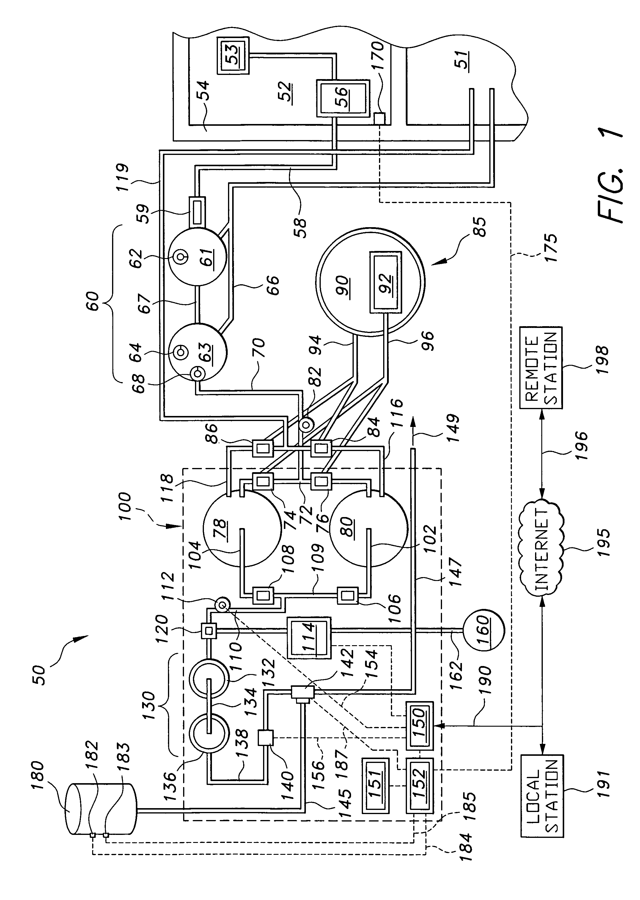
[0025]FIG. 1 schematically represents an exemplary embodiment of a proposed contaminated water treatment system 50. Power distribution lines are not shown for clarity. Untreated, contaminated water containing entrained cementitious particles accumulates in a storage container such as settling pit 52, which may be a final settling pit downstream from a series of pits starting with drying pit 51, as is known in the concrete production industry. For example, there may be one or more intermediary settling pits (not shown) between drying pit 51 and settling pit 52. The pits are separated by pit wall 54 and a weir (not shown), allowing fluid to pass between adjacent pits.

[0026]Pump 56 draws fluid from settling pit 52. Pump 56 may be any type of pump known for drawing water from a reservoir. For example, a floating suction line may be used. The floating suction line keeps the suction line opening 53 at a measured distance below the surface of the water and avoids the buildup of solids on t...


PUM

PropertyMeasurementUnit
diameteraaaaaaaaaa
diameteraaaaaaaaaa
diameteraaaaaaaaaa

Abstract

A method and system for treating a fluid containing entrained cementitious particles involves drawing the fluid from a storage location, pre-filtering the fluid, dividing the pre-filtered fluid into a flow of permeate and a flow of bypass by passing said pre-filtered fluid through a tangential flow filter. The permeate flow is fluid that has passed through a polymeric membrane filter media disposed in the tangential flow filter, while the bypass flow is flow exiting said tangential flow filter without passing through said membrane filter media. The system and method also includes a pH probe for testing the pH of the filtrate, and a metering pump operated by a controller which injects a neutralizing agent into the filtrate to reduce the alkalinity of the filtrate before discharge.

Description

BACKGROUND OF THE INVENTION[0001]1. Field of the Invention[0002]The present invention relates to a waste water treatment apparatus and process. In particular, the invention relates to a water treatment system and process for treating storm and process water in the concrete industry.[0003]2. Description of the Related Art[0004]The ready-mix concrete and concrete-related industries create large amounts of excess water contaminated by high amounts of suspended solids and a pH level near, or above, EPA hazardous guidelines. The contaminated excess water is either in the form of process water or storm water. Storm water is created by rain or snowmelt carrying off yard waste. Plant equipment, slump-racks, tank-fill stations and truck mixer-drum washout produce process water. It is this mixer-drum washout that creates the majority of the contaminated water. Mixer-drum washout water is created when clean water and / or cleaning solution is pumped into a cement mixer to wash out the concrete w...

Claims


Application Information

Patent Timeline
Patent Type & Authority Patents(United States)
IPC IPC(8): B01D36/02B01D29/88B01D35/00B01D61/04B01D61/08B01D61/12B01D61/18B01D61/22C02F1/00C02F1/44C02F1/66
CPCB01D61/04B01D61/147B01D61/12B01D61/18B01D61/22C02F1/444B01D61/08B01D61/025B01D2311/04C02F1/001C02F1/66C02F2103/001C02F2103/12C02F2201/008C02F2209/008C02F2209/06C02F2209/40B01D2311/18B01D2311/2649B01D61/1471
Inventor RHOADES, FRANK G.
Owner RHOADES FR G
Why Eureka
Try Eureka