Quantum communication apparatus and quantum communication method

a communication apparatus and quantum communication technology, applied in the field of quantum communication apparatus and quantum communication method, can solve the problems of inability to efficiently generate entanglement between distant sites, inability to amplify or relay state during transmission, and inability to perform entanglement connection. the effect of quick and efficient connection

Inactive Publication Date: 2008-07-29
KK TOSHIBA
View PDF7 Cites 5 Cited by
  • Summary
  • Abstract
  • Description
  • Claims
  • Application Information

AI Technical Summary

Benefits of technology

[0011]It is an object of the present invention to provide an apparatus and method that can generate entanglement between distant sites by quickly and efficiently performing entanglement connection without using any mechanical driving operation requiring much operation time.

Problems solved by technology

However, since a quantum state cannot be duplicated, it cannot be amplified or relayed during transmission.
This incapability of increasing the communication distance raises a common problem in putting the quantum communication into practice.
Conventionally, however, there have been no known apparatus or method that can efficiently generate entanglement between distant sites by quickly irradiating necessary sites with light necessary for entanglement connection without using any time-consuming mechanical driver.

Method used


Image

  • Quantum communication apparatus and quantum communication method
  • Quantum communication apparatus and quantum communication method
  • Quantum communication apparatus and quantum communication method

Examples


example 1

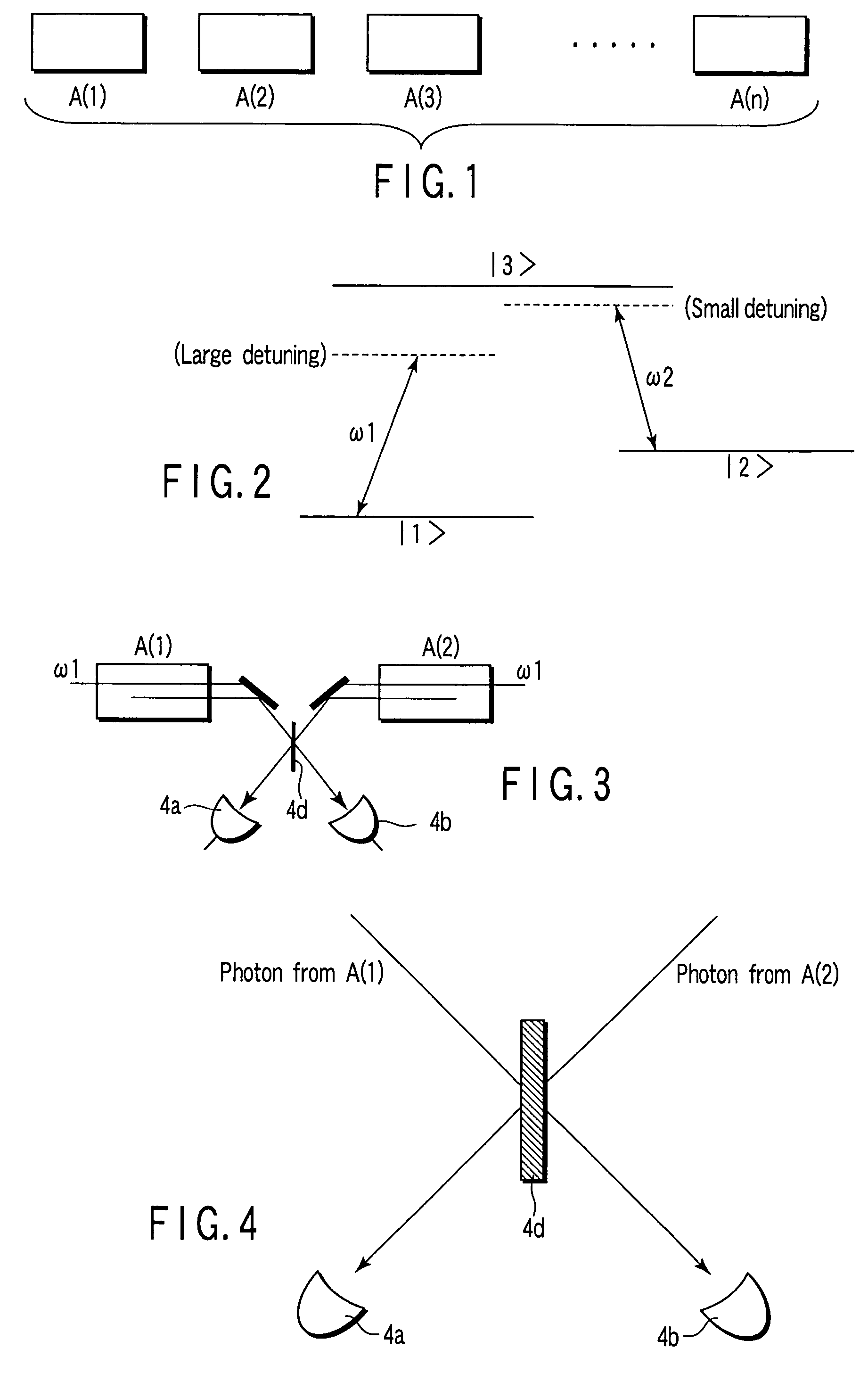
[0125]First, four 2 mm×2 mm×2 mm Y2SiO5 crystals dispersed with Pr3+ ions by 0.02% are prepared. The crystals are kept at a temperature of 1.4 K in cryostats 1 to 4 having optical windows.

[0126]Two ring dye laser sources are also prepared. One is a laser source whose frequency is stabilized to an angular frequency ω2 near 605.98 nm (16502.3 cm−1). The other is a laser source whose frequency is so stabilized as to emit light with angular frequency ω1=ω2−9.4×10¹³ rad / s lower than that of light emitted from the above laser source by 9.4×10¹³ rad / s (about 500 cm−1). The light from the former ring dye laser source resonates with a transition between 3H4(1), the lowest Stark level of Pr3+ in the crystal, and 1D2(1), an electronically excited state.

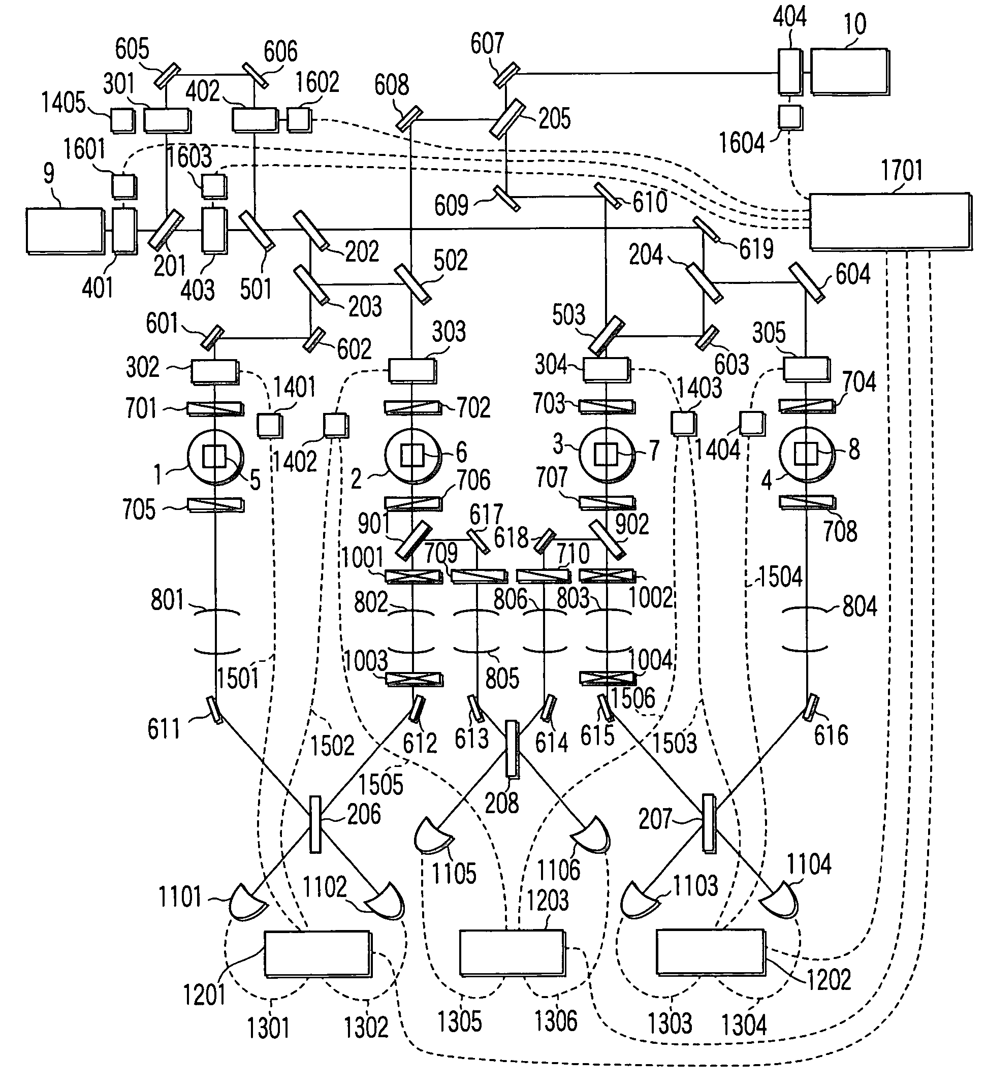
[0127]In Example 1, the apparatus shown in FIG. 9 is used. The crystals 5 to 8 as atomic ensembles A(1)-A(4) are irradiated with the respective laser beams and a generated photon is detected, thereby generating entanglement.

[0128]As shown in FIG...

example 2

[0159]In Example 1, the optical paths extending from the half mirror 501 to the acousto-optical devices 302 to 305 arranged for light applied to the crystals 5 to 8 and the optical paths extending from the electro-optical device 404 to the acousto-optical devices 303 and 304 are formed of a free space in which light is propagated according to mirrors that determine the direction of light. In contrast to this, in Example 2, light is made to propagate in optical fibers, and entanglement is generated between Pr3+ ion ensembles of crystals 5 and 8 as in Example 1.

[0160]The light transmitted through or reflected by the half mirror 501 is converged by the lens 2601 (see FIG. 11 hereinafter) and is incident on the optical fiber 2701 so as to propagate therein. The light transmitted through the electro-optical device 404 is converged by the lens 2602 and is incident on the optical fiber 2702 so as to propagate therein. The functions of the beam splitters or half mirrors in Example 1 are rep...

example 3

[0162]In Example 1, acousto-optical devices are used for the optical shutters 302 to 305. In contrast to this, in Example 3, the optical shutters 302 to 305 are replaced with shutters using electro-optical devices. As a consequence, the operation speed of the overall entanglement generation system can be improved, and the time necessary for entanglement connection can be shortened as compared with Example 1. The time necessary for entanglement generation except for an initialization process for crystals, in particular, can be shortened to 1 / 10. That is, the construction in this Example 3 is effective for entanglement generation between distant sites based on multistage entanglement connection.


PUM


Abstract

A quantum communication apparatus is used in operations to generate entanglement between the two physical system ensembles and operations to extend the distance between entangled ensembles by connecting pairs of entangled ensembles. The apparatus uses only passive elements without any actuating parts, active devices having no mechanically actuating parts, such as an electro-optical device capable of ultrahigh-speed operation, and a laser source capable of generating high-speed pulse trains or a continuous wave laser source. The apparatus can rapidly execute light irradiation necessary for entanglement generation and connection, and detection of a generated photon at the needed sites within a decoherence time of the physical system.

Description

CROSS-REFERENCE TO RELATED APPLICATIONS[0001]This application is based upon and claims the benefit of priority from the prior Japanese Patent Application No. 2002-290107, filed Oct. 2, 2002, the entire contents of which are incorporated herein by reference.BACKGROUND OF THE INVENTION[0002]1. Field of the Invention[0003]The present invention relates to an apparatus and a method of quickly generating entanglement between distant sites before occurrence of decoherence to enable quantum communication such as quantum teleportation or quantum cryptography between distant sites.[0004]2. Description of the Related Art[0005]In conventionally proposed quantum communication such as quantum teleportation or quantum cryptography, two light beams in an entanglement state (quantum mechanically entangled state) generated in one place are transmitted to both the sender and the receiver so as to perform communication by using a quantum correlation existing between the two light beams (A. Furusawa et ...

Claims


Application Information

Patent Timeline
Patent Type & Authority Patents(United States)
IPC IPC(8): H04K1/00G02B6/28H04B10/30H04L9/08
CPCH04L9/0852H04B10/70
Inventor ICHIMURA, KOUICHISHIOKAWA, NORITSUGU
Owner KK TOSHIBA
Why Eureka
Try Eureka