Thermally stable diamond cutting elements in roller cone drill bits

a technology of diamond inserts and roller cone drill bits, which is applied in the direction of sealing/packing, application, and borehole/well accessories. it can solve the problems of impact wear, wear, and wear of pdc inserts, and achieve the effect of reducing the risk of impact damag

Inactive Publication Date: 2008-08-05
SMITH INT INC
View PDF19 Cites 39 Cited by
  • Summary
  • Abstract
  • Description
  • Claims
  • Application Information

AI Technical Summary

Problems solved by technology

PDC inserts are typically subject to three types of wear: abrasive and erosive wear, impact wear, and wear resulting from thermal damage.
Abrasive wear occurs when the edges of individual diamond grains are gradually removed through impact with an earth formation.
Abrasive wear can also result in cleavage fracturing along the entire plane of a diamond grain.
PDC inserts are also subject to thermal damage due to heat produced at the contact point between the insert and the formation.
This differential in thermal expansion rates produces large compressive and tensile stresses on the PDC insert and can initiate stress risers that cause delamination of the diamond table from the substrate.
The cobalt thermally expands significantly faster than the diamond causing cracks to form and propagate in the lattice structure of the diamond table, eventually leading to deterioration of the diamond table and ineffectiveness of the PDC insert.
Maintaining the WOB and rotary speed of a drill bit such that the critical penetrating force is not exceeded prolongs the life of the PDC insert, but at the same time reduces the rate of penetration (ROP) of the drill bit.
The heat generated from the PDC insert's contact with an earth formation can differ depending on the type of formation being drilled, and if a particular formation tends to generate very high temperatures, the viable ROP of bits with PDC inserts may be below the desired ROP and the drill bit's effectiveness severely limited.
TSD formed through the removal of all or most of the cobalt catalyst is thermally stable up to a temperature of 1200° Celcius (2192° Fahrenheit), but is more brittle and vulnerable to shear and tensile stresses than PDC.

Method used


Image

  • Thermally stable diamond cutting elements in roller cone drill bits
  • Thermally stable diamond cutting elements in roller cone drill bits
  • Thermally stable diamond cutting elements in roller cone drill bits

Examples


Embodiment Construction

[0038]During the course of drilling, the life of a drill bit is often limited by the failure rate of the cutting elements mounted on the bit. Cutting elements may fail at different rates depending on a variety of factors. Such factors include, for example, the geometry of a cutting element, the location of a cutting element on a bit, a cutting element's material properties, and so forth.

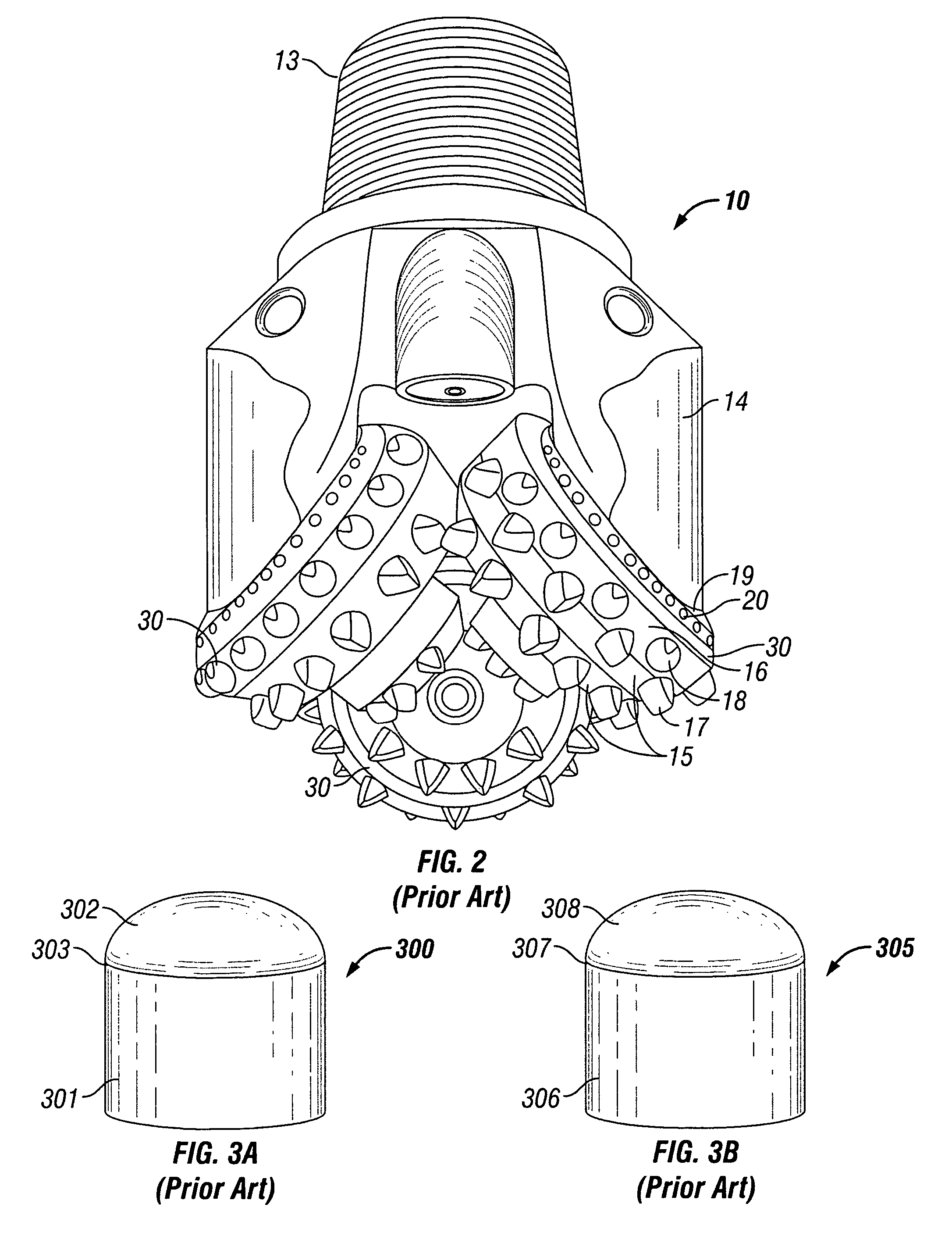
[0039]The relative radial position of a cutting element along a roller cone's rotational axis is an important factor affecting the extent of wear that the cutting element will experience during drilling, and consequently, the life of the cutting element. Cutting elements disposed on the outer rows of a roller cone, in particular the gage and heel rows, experience more abrasive and impact wear than cutting elements disposed on the inner rows of a roller cone. Gage row cutting elements serve the dual functions of cutting the bottom of a wellbore and cutting and maintaining the wellbore diameter or the ...


PUM

PropertyMeasurementUnit
depthaaaaaaaaaa
depthaaaaaaaaaa
widthaaaaaaaaaa

Abstract

A roller cone drill bit for drilling earth formations includes a bit body having at least one roller cone rotably attached to the bit body and a plurality of cutting elements disposed on the at least one roller cone in a plurality of rows arranged circumferentially around the at least one roller cone, wherein at least one cutting element in the gage row, the heel row, or a surface of the at least one roller cone bounded by the gage and heel rows comprises thermally stable polycrystalline diamond or a thermally stable polycrystalline diamond composite. The at least one cutting element may be a TSD insert or a TSD composite insert and may be formed by brazing, sintering, or bonding by other technologies known in the art a thermally stable polycrystalline diamond table to a substrate. The interface between the diamond table and the substrate may be non-planar. A roller cone drill bit includes a bit body, at least one roller cone rotably attached to the bit body, and a plurality of cutting elements disposed on the at least one roller cone, where at least one of the plurality of cutting elements comprises thermally stable polycrystalline diamond or a thermally stable polycrystalline diamond composite and a cutting surface, wherein at least a portion of the cutting surface is contoured.

Description

BACKGROUND OF INVENTION[0001]1. Field of the Invention[0002]The invention relates generally to roller cone drill bits for drilling earth formations. More specifically, the invention relates to thermally stable diamond inserts in roller cone drill bits.[0003]2. Background Art[0004]Roller cone drill bits are commonly used in oil and gas drilling applications. FIG. 1 shows a conventional drilling apparatus for drilling a wellbore. The drilling system 1 includes a drill rig 2 that rotates a drill string 3 that extends downward into a wellbore 5 and is connected to a roller cone drill bit 4.[0005]FIG. 2 shows a typical roller cone drill bit in more detail. The roller cone drill bit includes a top end 13 threaded for attachment to a drill string and a bit body 10 having legs 14 depending therefrom, to which roller cones 30 are attached. The roller cones 30 are able to rotate with respect to the bit body 10. Cutting elements 17, 18, 19 are disposed on the roller cones 30 and are typically ...

Claims


Application Information

Patent Timeline
Patent Type & Authority Patents(United States)
IPC IPC(8): E21B10/00
CPCE21B10/16E21B17/1092E21B10/567E21B10/52
Inventor KESHAVAN, MADAPUSI K.GRIFFO, ANTHONY
Owner SMITH INT INC
Why Eureka
Try Eureka