Fluid treatment system

a treatment system and fluid technology, applied in liquid separation, water/sludge/sewage treatment, instruments, etc., can solve the problems of high capital cost of reactors, difficult access, and manifested problems, and achieve the effect of increasing fluid flow velocity and decreasing fluid flow velocity

Active Publication Date: 2008-08-05
TROJAN TECH
View PDF12 Cites 33 Cited by
  • Summary
  • Abstract
  • Description
  • Claims
  • Application Information

AI Technical Summary

Benefits of technology

[0068]Thus, the present inventors have discovered a fluid treatment system having one or more of the following advantages:
[0083]In the present fluid treatment system, it is possible to incorporate a so-called transition region upstream and / or downstream of the fluid treatment zone. Preferably, such a transition region serves to funnel or otherwise transition the flow of fluid in a manner such that cross-sectional area of the flow of fluid orthogonal to the direction of fluid flow is: (i) increased (if the transition region is placed upstream of the fluid treatment zone) thereby decreasing fluid flow velocity, or (ii) decreased (if the transition region is placed downstream of the fluid treatment zone) thereby increasing fluid flow velocity.

Problems solved by technology

Certain problems existed with these earlier designs.
These problems were manifested particularly when applied to large open flow treatment systems which are typical of larger scale municipal waste water or potable water treatment plants.
Thus, these types of reactors had associated with them the following problems:relatively high capital cost of reactor;difficult accessibility to submerged reactor and / or wetted equipment (lamps, sleeve cleaners, etc);difficulties associated with removal of fouling materials from fluid treatment equipment;relatively low fluid disinfection efficiency, and / orfull redundancy of equipment was required for maintenance of wetted components (sleeves, lamps and the like).
Since the design of the system inherently comprised a free-surface flow of fluid, there were constraints on the maximum flow each lamp or lamp array could handle before either one or other hydraulically adjoined arrays would be adversely affected by changes in water elevation.
At higher flows or significant changes in the flow, the unrestrained or free-surface flow of fluid would be allowed to change the treatment volume and cross-sectional shape of the fluid flow, thereby rendering the reactor relatively ineffective.
The problem here was that, with less powerful lamps, a relatively large number of lamps was required to treat the same volume of fluid flow.
Thus, the inherent cost of the system would be unduly large and / or not competitive with the additional features of automatic lamp sleeve cleaning and large fluid volume treatment systems.
In order to use the more powerful lamps (e.g. medium pressure UV lamps), the hydraulic loading per lamp during use of the system would be increased to an extent that the treatment volume / cross-sectional area of the fluid in the reactor would significantly change if the reactor surface was not confined on all surfaces, and hence such a system would be rendered relatively ineffective.
These significantly shorter and more powerful lamps inherently are characterized by being less efficient in converting electrical energy to UV energy.
The cost associated with the equipment necessary to physically access and support these lamps was significant.
Unfortunately, for the treatment of large volumes of fluid, arrangement (ii) can be disadvantageous for a number of reasons.
Specifically, implementation of arrangement (ii) requires a relatively large “footprint” or space to house the radiation sources.
Further, the use of a large number of radiation sources in arrangement (ii) creates a relatively large coefficient of drag resulting in a relatively large hydraulic pressure loss / gradient over the length of the fluid treatment system.
Still further, the use of a large number of radiation sources in arrangement (ii) can produce vortex effects (these effects are discussed in more detail hereinbelow) resulting in forced oscillation of the radiation sources—such forced oscillation increases the likelihood of breakage of the radiation source and / or protective sleeve (if present).

Method used


Image

  • Fluid treatment system
  • Fluid treatment system
  • Fluid treatment system

Examples


Embodiment Construction

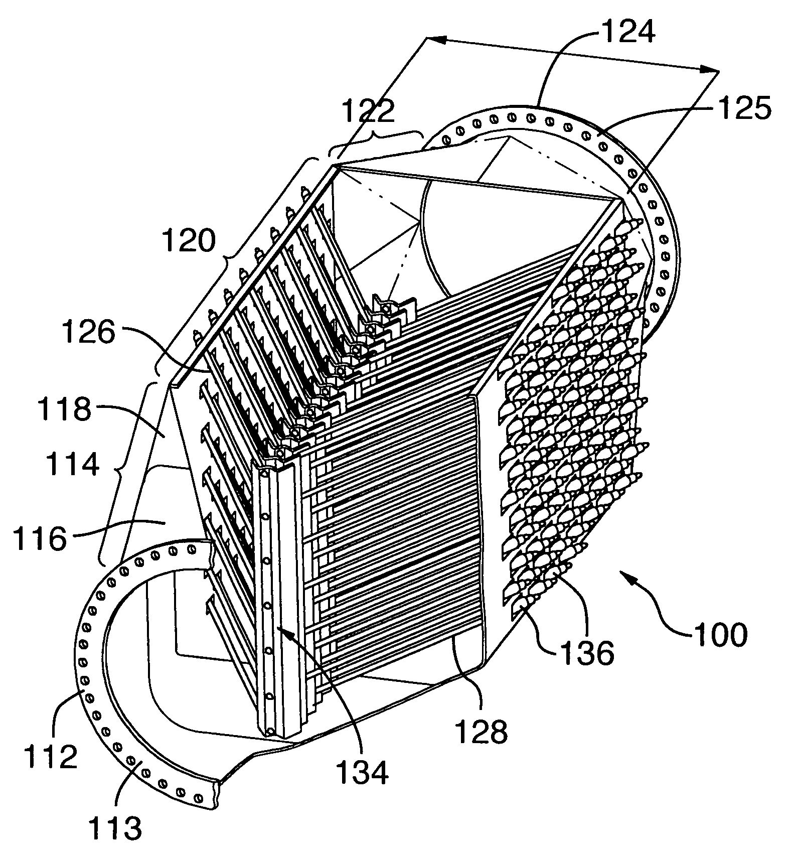
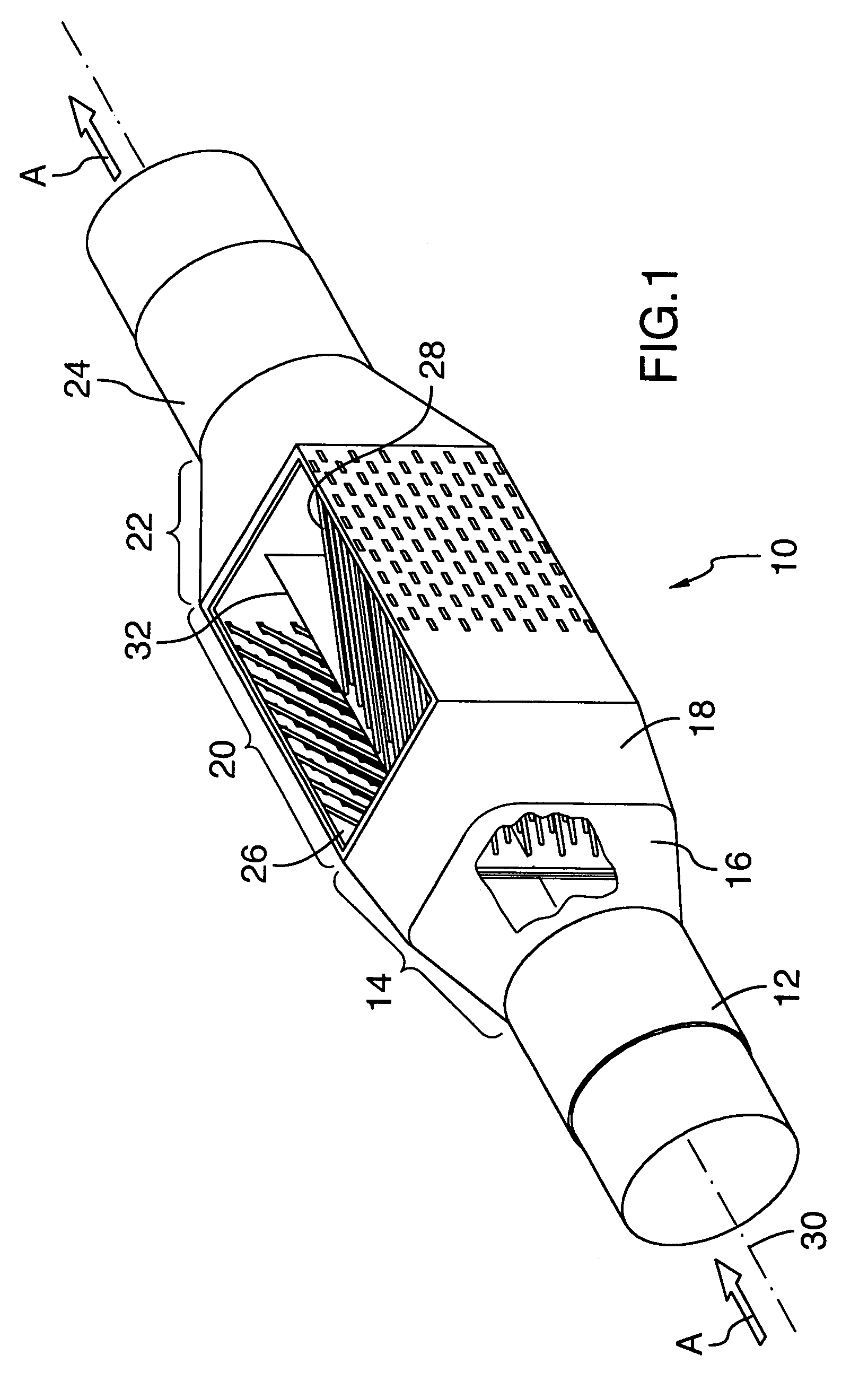
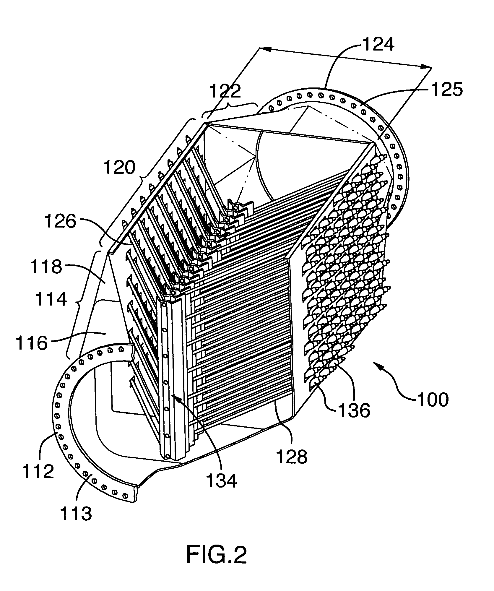
[0102]With reference to FIG. 1, there is illustrated a fluid treatment system 10. Fluid treatment system 10 comprises an inlet 12 and an outlet 24. Disposed between inlet 12 and outlet 24 is a fluid treatment zone 20.

[0103]Fluid treatment zone 20 is interconnected to inlet 12 by an inlet transition zone 14 comprising a first transition region 16 and intermediate transition region 18. Outlet 24 is interconnected to fluid treatment zone 20 by an outlet transition zone 22.

[0104]As illustrated, fluid passes through fluid treatment system 10 (including fluid treatment zone 20) in the direction of arrow A.

[0105]As shown, each of inlet 12, inlet transition zone 14, fluid treatment zone 20, outlet transition zone 22 and outlet 24 have a closed cross-section. The use of the term “closed cross-section” is intended to mean an enclosure which bounds a flow of fluid on all sides and / or surfaces.

[0106]As shown, inlet 12 and outlet 24 have a circular cross-section much like a conventional pipe arr...


PUM

PropertyMeasurementUnit
angleaaaaaaaaaa
angleaaaaaaaaaa
angleaaaaaaaaaa

Abstract

The present invention relates to a fluid treatment system comprising: an inlet; an outlet; and a fluid treatment zone disposed between the inlet and the outlet. The fluid treatment zone has disposed therein: (i) an elongate first radiation source assembly having a first longitudinal axis, and (ii) an elongate second radiation source assembly having a second longitudinal axis. The first longitudinal axis and the second longitudinal axis are non-parallel to each other and to a direction of fluid flow through the fluid treatment zone. The present fluid treatment system has a number of advantages including: it can treat large volumes of fluid (e.g., wastewater, drinking water or the like); it requires a relatively small “footprint”; it results in a relatively lower coefficient of drag resulting in an improved hydraulic pressure loss / gradient over the length of the fluid treatment system; and it results in relatively lower (or no) forced oscillation of the radiation sources thereby obviating or mitigating of breakage of the radiation source and / or protective sleeve (if present). Other advantages are discussed in the specification.

Description

CROSS-REFERENCE TO RELATED APPLICATION[0001]The present application claims the benefit under 35 U.S.C. §119(e) of provisional patent application Ser. No. 60 / 552,185 filed on Mar. 12, 2004 and Ser. No. 60 / 613,215 filed on Sep. 28, 2004, the contents of each of which are hereby incorporated by reference.BACKGROUND OF THE INVENTION[0002]1. Field of the Invention[0003]In one of its aspects, the present invention relates to a fluid treatment system, more particularly, an ultraviolet radiation water treatment system. In another of its aspects, the present invention relates to a method for treating a fluid, more particularly a method for irradiating water.[0004]2. Description of the Prior Art[0005]Fluid treatment systems are generally known in the art. More particularly, ultraviolet (UV) radiation fluid treatment systems are generally known in the art. Early treatment systems comprised a fully enclosed chamber design containing one or more radiation (preferably UV) lamps. Certain problems ...

Claims


Application Information

Patent Timeline
Patent Type & Authority Patents(United States)
IPC IPC(8): B01D17/00A61L2/10B01D17/06C02F1/30C02F1/32
CPCA61L2/10C02F1/325C02F1/32C02F1/006C02F2201/3225C02F2201/3228C02F2201/324C02F2201/328C02F2201/3227
Inventor FROM, WESTCHAVDAROV, BOYKOMARCU, MIKEGRATTON, RICHARDOLSON, DAVIDFRASER, JIMKEZELE, DUSKO A.
Owner TROJAN TECH
Why Eureka
Try Eureka