Image processing device, image processing method and recording medium

a technology of image processing and image, applied in the direction of image enhancement, printers, instruments, etc., can solve the problems of difficult to eliminate defect portions in output images, parts are simply reduced, and foreign matter is clearly visible as a defect portion, etc., to suppress uneven correction accuracy, accurate correction, and high degree of accuracy

Inactive Publication Date: 2008-08-05
FUJIFILM HLDG CORP +1
View PDF7 Cites 27 Cited by
  • Summary
  • Abstract
  • Description
  • Claims
  • Application Information

AI Technical Summary

Benefits of technology

[0054]In the twelfth aspect of the present invention, a feature amount representing a difference between the refractive indexes of visible light and non-visible light in an image recording material is acquired either on the basis of the type of image recording material, or by calculating a ratio of a value obtained when high frequency components are extracted from a change in the amount of transmitted or reflected non-visible light in an area adjacent to the defect portion when non-visible light is irradiated onto the image recording material and a value obtained when high frequency components are extracted from a change in an amount of transmitted or reflected visible light in an area adjacent to the defect portion when visible light is irradiated onto the image recording material. Therefore, it is possible to determine brightness alteration amounts for accurately correcting changes in the amount of transmitted or reflected visible light caused by scratches and the like on the image recording material by calculating the brightness correction amounts using the above feature amount.
[0055]In the image processing method according to the thirteenth aspect of the present invention: a defect portion in an image represented by image information is detected; based on a feature amount in the defect portion, either a correction method that should be applied to correct the defect portion is selected from a plurality of correction methods, or ranges of application of each of two or more correction methods to be applied to the correction of the defect portion are decided; and either correction of the defect portion is performed by applying the selected correction method to the image information, or correction of the defect portion is performed by applying each of the two or more correction methods in the application ranges decided to the image information. Therefore, in the same way as in the first aspect of the present invention, it is possible to correct various defect portions each with a high degree of accuracy.
[0056]In the image processing method according to the fourteenth aspect of the present invention, the following are performed. Namely, image feature amounts are calculated for defect portions present in an image represented by image information along a plurality of different directions running from inside the defect portion. In addition, correction values for correcting the defect portions are obtained by interpolation from information of areas in a predetermined direction on the image relative to the defect portion for each of the plurality of directions. Final correction values are determined from the correction values for each direction based on the image feature amounts in each direction, and correction of the defect portions is performed on the image information using the final correction values. Therefore, in the same way as in the eighth aspect of the present invention, it is possible to suppress unevenness in the accuracy of the correction when correcting defect portions using the interpolation method.
[0057]In the image processing method according to the fifteenth aspect of the present invention, a brightness alteration amount for correcting a defect portion of an image that is detected from image information representing the image which is recorded on an image recording material is calculated based on the amount of transmitted or reflected non-visible light in the area adjacent to the defect portion when non-visible light is irradiated onto the image recording material, and on the difference in the refractive indexes of visible light and non-visible light in the image recording material. Moreover, the image information is corrected so that the brightness of the defect portion in the image represented by the image information changes by the brightness change amount calculated by the calculation device. Therefore, in the same way as in the eleventh aspect of the present invention, it is possible to correct the defect portion with a high degree of accuracy using the brightness adjustment method.

Problems solved by technology

Moreover, if foreign matter such as dust or the like becomes attached to the surface of a photographic film, the foreign matter is clearly visible as a defect portion.
However, in this technology, it is difficult to eliminate defect portions in an output image (i.e. in an image recorded by exposure on photographic paper), and the defect portions are simply reduced slightly (i.e. made less visible).
However, each one of these correction methods has a weak point.
Namely, in the interpolation method, because interpolation is performed from changes in the density in the surrounding area adjacent to the defect portion with it being assumed that the density of the original image changes smoothly and continuously between the defect portion and the surrounding area adjacent to the defect portions, then if, for example, the change in the density is originally complex within the defect portion, the accuracy of the interpolation calculation is low (i.e. the accuracy with which the density of the original image is reproduced) and in some cases the result of the correction is somewhat inappropriate and gives a sense of incongruity to the person looking at the output result.
Because the proper interpolation direction enabling the defect portion to be properly corrected is different depending on the defect portion, there is a drawback that there is a great amount of unevenness in the accuracy of the correction depending on the defect portion to be corrected.
In contrast to this, because the brightness adjustment method only adjusts the brightness and does not change the color of a defect portion, it is difficult using this method to accurately correct defect portions such as those described above.
In the vignetting method, because the defect portions are vignetted by reducing high frequency components of the spatial frequency in the defect portion and the area surrounding the defect portions, this method is not suitable for correcting defect portions caused by deep scratches or by the presence of comparatively large-sized foreign matter.
Namely, in order to correct defect portions such as these, it is necessary to enlarge the degree of vignetting of the defect portions which tends to lower the image quality of the image.
As can thus be seen, no matter which of the various correction methods described above is used, it is difficult to correct with any accuracy all of the varied types of defect portions which all have different features to each other.
It is possible to correct these defect portions in the same way as the defect portions caused by foreign matter and scratching on a photographic film, however, no matter which of the above correction methods is used for such corrections, it is still difficult to accurately correct each one of the various types of defect portions.

Method used


Image

  • Image processing device, image processing method and recording medium
  • Image processing device, image processing method and recording medium
  • Image processing device, image processing method and recording medium

Examples


Embodiment Construction

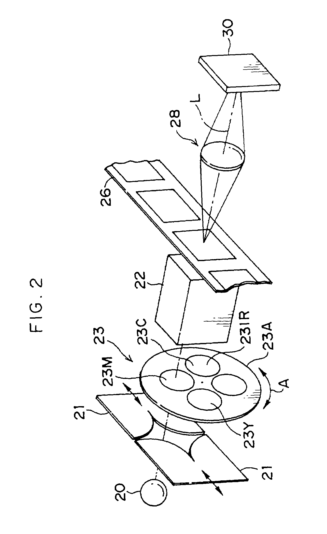
[0081]A description will now be given in detail of the embodiment of the present invention with reference made to the drawings. Note that the description below is of an example in which defect portions, caused by scratching or foreign matter present on the surface of a photographic film, are corrected.

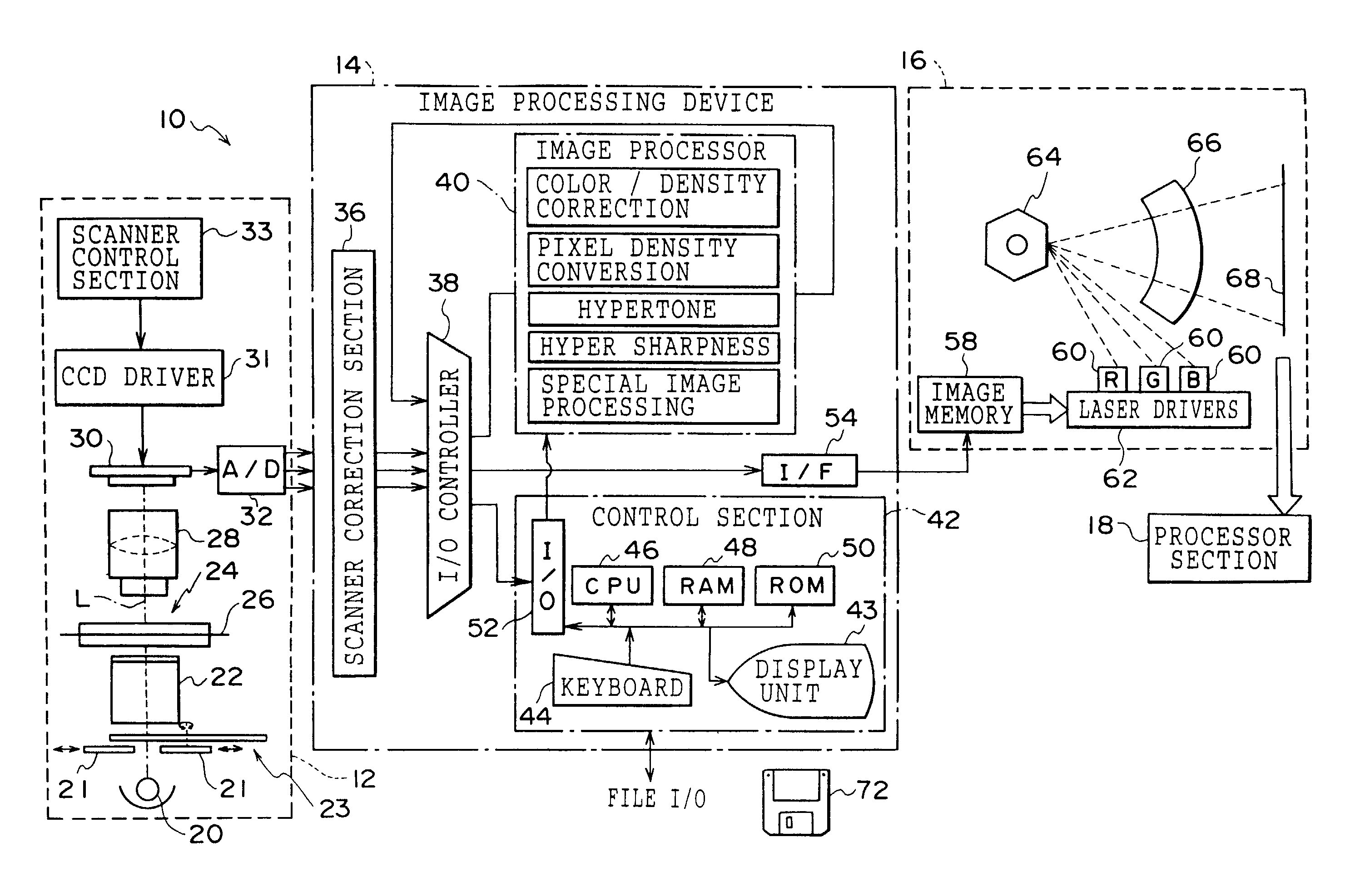
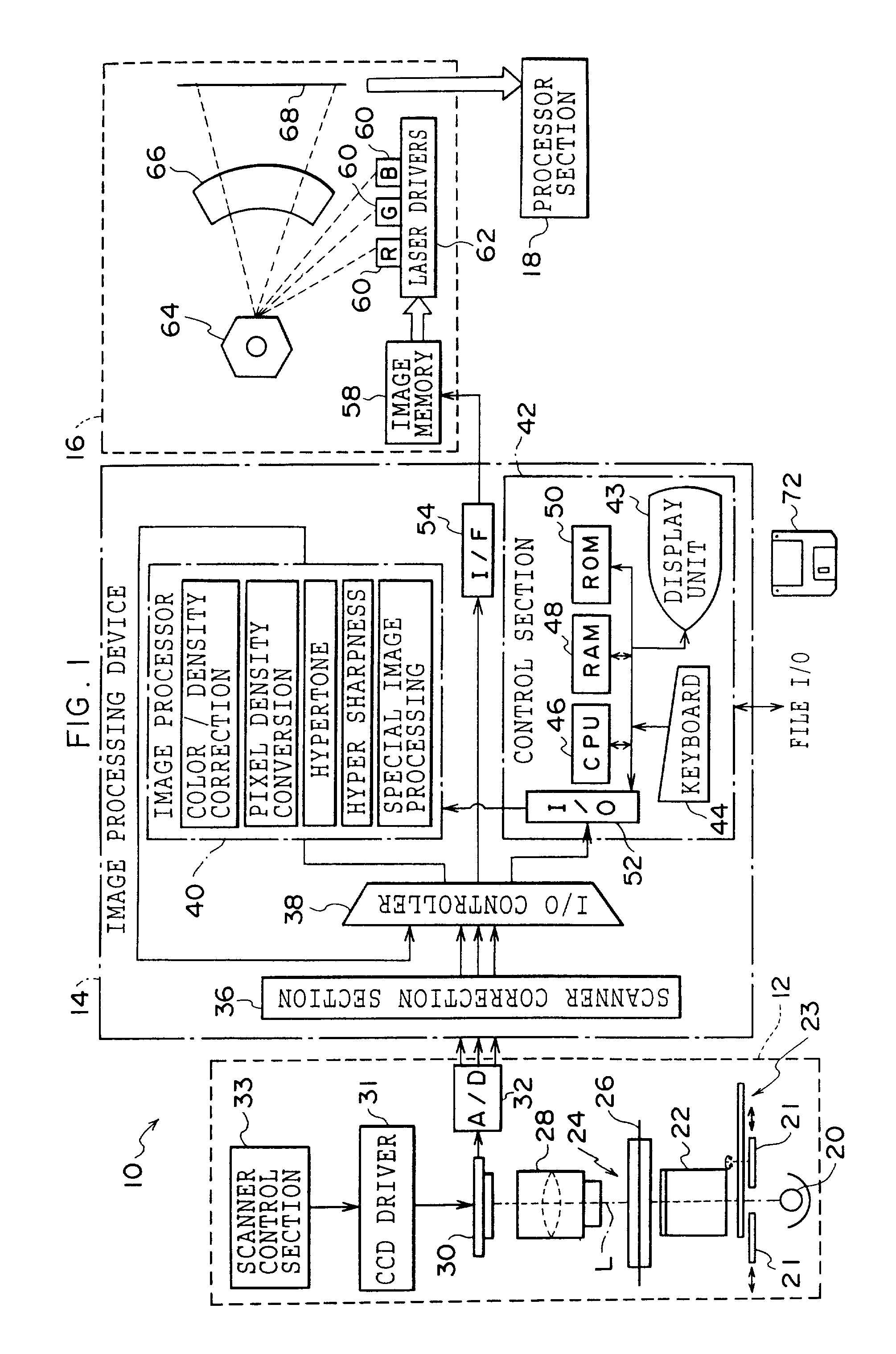
[0082]FIG. 1 shows an image processing system 10 according to the present embodiment. The image processing system 10 is constructed from a film scanner 12, an image processing device 14, and a printer 16 connected in a series. Note that the film scanner 12 and the image processing device 14 correspond to the image processing device of the present invention.

[0083]The film scanner 12 reads an image (e.g. a negative or positive image of a photographed subject made visible by developing processing) recorded on a photographic photosensitive material (referred to below simply as a photographic film) such as a photographic film (e.g. negative or reversal). The film scanner 12 also outputs ima...


PUM


Abstract

The present invention provides an image processing device, an image processing method, and a recording medium that enable various defect portions to be accurately corrected. R, G, B, and IR are respectively read in an image recorded on a photographic film and transverse chromatic aberration correction is performed on each of the R, G, B, and IR image data. Subsequently, defect portions in the image being processed are detected based on the IR data, and predetermined feature amounts are calculated for the image portion being processed. Based on the results of this calculation, either one of the interpolation method or brightness adjustment method is selected as the correction method for the defect portion being processed, or the ranges in which each of these correction methods is to be applied are decided. Consequently, either one of the two correction methods or both correction methods are applied and the correction values decided, and the final correction values are then determined.

Description

BACKGROUND OF THE INVENTION[0001]1. Field of the Invention[0002]The present invention relates to an image processing device, an image processing method, and a recording medium. In particular, the present invention relates to an image processing device for correcting defect portions in an image represented by image information, an image processing method that can be applied to the image processing device, and a recording medium on which is recorded a program for enabling a computer to function as the image processing device.[0003]2. Description of the Related Art[0004]Because of the handling thereof, sometimes the emulsion surface and the back surface (i.e. the rear surface of the emulsion surface) of a photographic film become scratched. If scratches are formed within locations corresponding to the image recording area of a photographic film, and if an attempt is made to output (i.e. by recording the image on an image recording material such as photographic paper or the like, or by ...

Claims


Application Information

Patent Timeline
Patent Type & Authority Patents(United States)
IPC IPC(8): H04N7/18G03B27/73H04N1/19G06T5/00H04N1/409
CPCG03B27/73H04N1/4097G06T5/005
Inventor YAMAGUCHI, HIROSHI
Owner FUJIFILM HLDG CORP
Why Eureka
Try Eureka