Control system for plant and internal combustion engine

a control system and plant technology, applied in electrical control, program control, instruments, etc., can solve the problems of reducing the accuracy of identification of model parameters, increasing the modeling errors of plant models, and unable to directly identify the model parameters of plant models directly from experimental data of the plant, so as to improve the accuracy and the response of control

Inactive Publication Date: 2008-08-05
HONDA MOTOR CO LTD
View PDF17 Cites 6 Cited by
  • Summary
  • Abstract
  • Description
  • Claims
  • Application Information

AI Technical Summary

Benefits of technology

[0019]According to this control system, the control inputs are calculated as non-interacting inputs for causing the control amounts to follow the target values, the non-interacting inputs eliminating the mutual interaction, with a predetermined control algorithm formed based on a plant model formed by modeling a plant into a discrete-time system model, the predetermined control algorithm including a combination of a predetermined response-specifying control algorithm and a predetermined non-interacting control algorithm. Therefore, it is possible to cause the control amounts to accurately follow the target values, respectively, while eliminating the mutual interaction between the control inputs and the control amounts. Further, since the discrete-time system model is used in calculation of the non-interacting inputs, modeling errors can be reduced compared with the conventional control system employing the continuous-time system model, whereby it is possible to ensure a large margin of the stability of control while setting the controller gains to higher values. Furthermore, since the discrete-time system model is used, differently from the conventional control system employing the continuous-time system model, there is no need to employ differential values of the control amounts as variables forming switching functions, whereby even when the control period is short, it is possible to ensure robustness, which is the advantageous feature of the response-specifying control algorithm, such as a sliding mode control algorithm. As described above, the controllability and the control accuracy can be improved.
[0061]According to this control system, one of the control amounts is the boost pressure; one of the control inputs is a boost pressure control value for controlling the boost pressure by the supercharger; the operating condition parameter is valve timing of the intake valve; and the boost pressure control value is calculated as one of the non-interacting inputs according to at least one of the valve timing of the intake valve, the control amounts, and the control inputs. Generally, when the boost pressure is controlled by the supercharger, there is a relationship between the valve timing of the intake valve and the control characteristics of the boost pressure that when the valve timing of the intake valves has changed, the control characteristics of the boost pressure also change. Therefore, there is a fear that if the control of the boost pressure is carried out independently of the valve timing of the intake valve, it becomes impossible not only to properly control the boost pressure but also to eliminate the mutual interaction between the control inputs and the control amounts. In contrast, according to the control system, it is possible to properly control the boost pressure, while eliminating the mutual interaction, since the boost pressure control value as one of the non-interacting inputs is calculated according to the valve timing of the intake valve. As a result, it is possible to further enhance the accuracy and the response of the control.

Problems solved by technology

In the above conventional control system, since the continuous-time system models are used as the plant models, it is difficult to directly identify model parameters of the plant models directly from experimental data of the plant.
Such approximate transform degrades the accuracy of identification of the model parameters.
Furthermore, it is required to approximately transform the discrete-time system models to the continuous-time system models again, which increases modeling errors in the plant models.
Consequently, to ensure a large margin of the stability of the control, it is necessary to reduce the controller gains, resulting in further degraded controllability and control accuracy.
Furthermore, when the continuous-time system models are employed, differential values of the control amounts are used as variables constituting switching functions, and when the control period is short, such differential values fail to indicate the rates of change in the control amounts, and are placed in a state close to noise components.
As a result, the robustness as the advantageous feature of the sliding mode control is lost, which further degrades the controllability and the control accuracy.
Therefore, in the above state of control of the intake air amount, if the throttle valve opening is controlled to a considerably small value so as to change the intake pipe pressure to a very negative value, the intake air amount varies due to the influence of the control of the throttle valve opening, which makes it impossible to properly control the intake air amount to the target value.
Inversely, if the intake air amount is controlled, the intake pipe pressure varies due to the influence of the control of the intake air amount, which makes it impossible to properly control the intake pipe pressure to the target value.

Method used


Image

  • Control system for plant and internal combustion engine
  • Control system for plant and internal combustion engine
  • Control system for plant and internal combustion engine

Examples


first embodiment

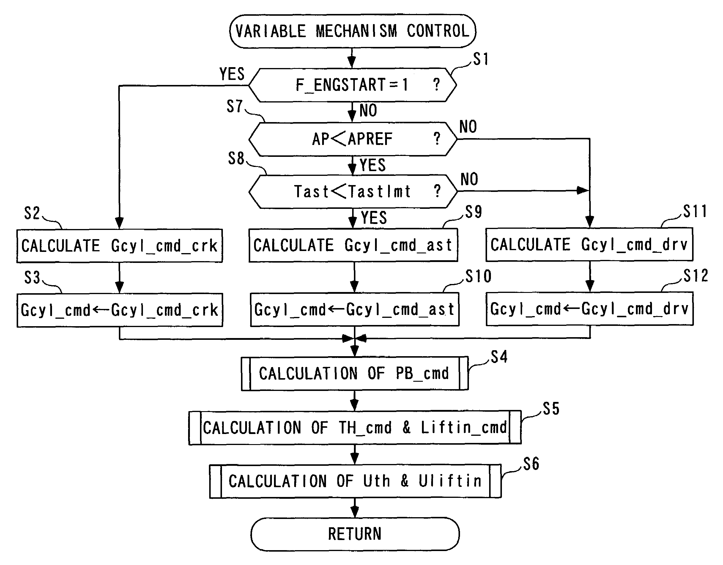
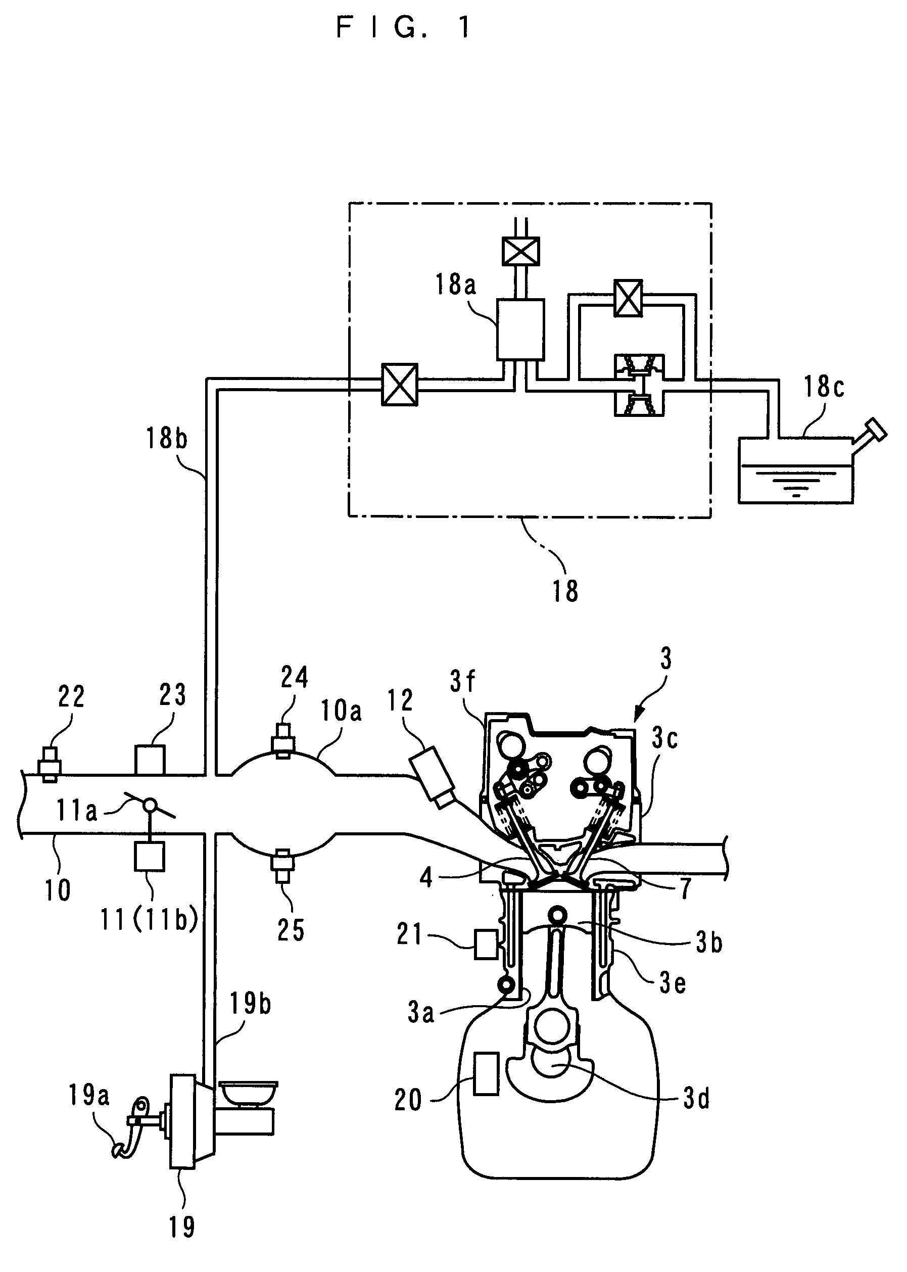
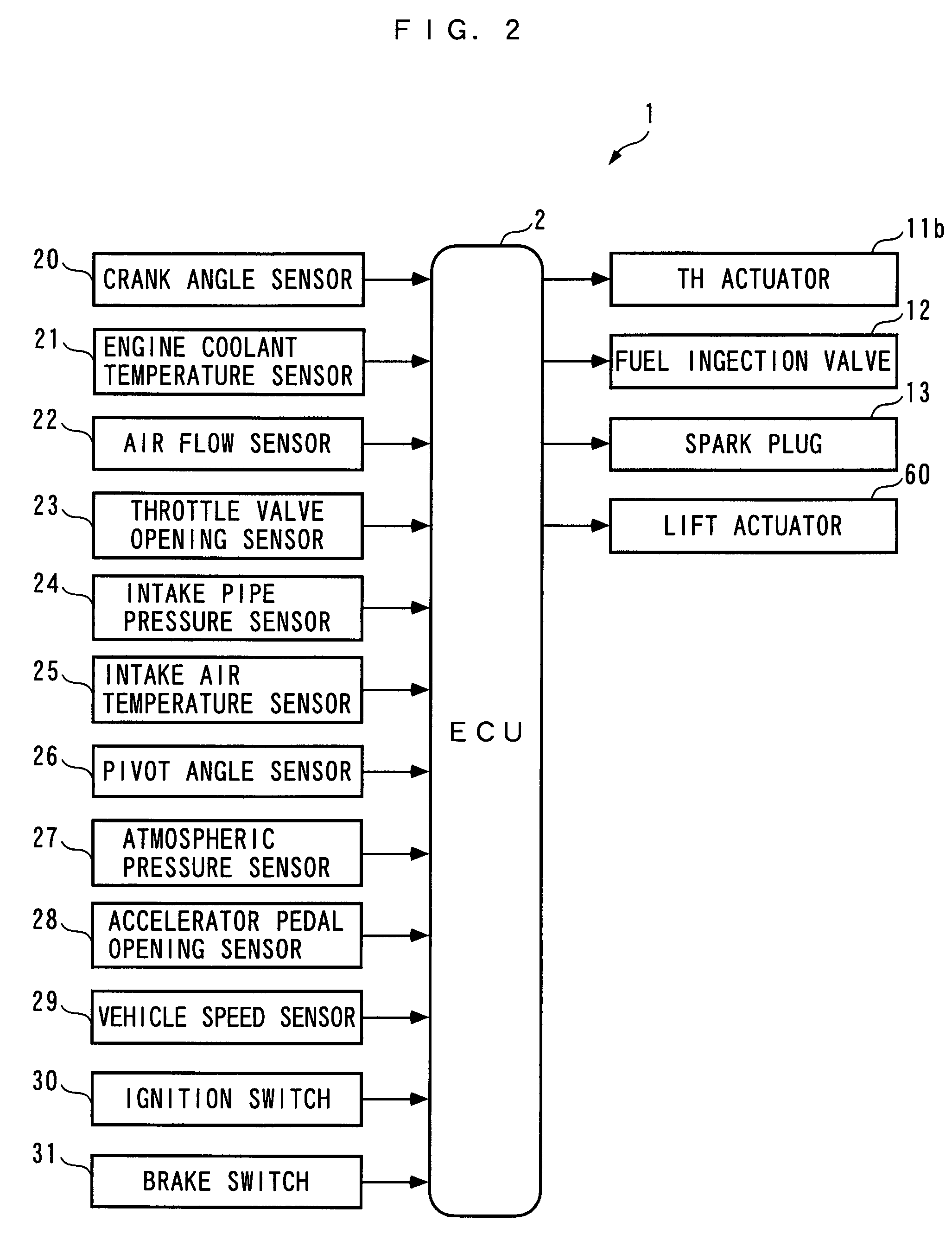
[0101]Hereafter, a control system according to the present invention will be described with reference to drawings. The control system 1 includes an ECU 2, as shown in FIG. 2. As described hereinafter, the ECU 2 carries out control processes, such as a variable mechanism control process, depending on operating conditions of an internal combustion engine (hereinafter simply referred to as “the engine”) 3.

[0102]Referring to FIGS. 1 and 3, the engine 3 is an in-line four-cylinder gasoline engine having four pairs of cylinders 3a and pistons 3b (only one pair of which is shown), and installed on a vehicle, not shown. The engine 3 includes an intake valve 4 and an exhaust valve 7 provided for each cylinder 3a, for opening and closing an intake port and an exhaust port thereof, respectively, an intake camshaft 5 and intake cams 6 that actuate the intake valves 4, a variable intake valve-actuating mechanism 40 that actuates the intake valves 4 to open and close the same, an exhaust camshaft...

second embodiment

[0267]Next, a description will be given of the results of simulations of variable mechanism control (hereinafter referred to as “the results of the control”) performed by the control system 1A according to the FIG. 26 shows the results of the control, obtained when there are modeling errors, i.e. when calculation errors occur in the calculation of the non-interacting parameters Fth and Flf.

[0268]As is clear from FIG. 26, according to the results of the control, when the target intake air amount Gcyl_cmd is changed stepwise to a larger value in the state of the target intake pipe pressure PB_cmd being held constant (time t31), the degree of difference generated between the intake pipe pressure PB and the target intake pipe pressure PB_cmd is smaller than in the FIG. 23 results of the control by the first embodiment, obtained when there are modeling errors, and the intake air amount Gcyl is not overshot with respect to the target intake air amount Gcyl_cmd, so that the control accura...

third embodiment

[0303]Next, a description will be given of the results of simulations of variable mechanism control (hereinafter referred to as “the results of the control”) performed by the control system 1B according to the FIG. 31 shows the results of the control, obtained when there are modeling errors, i.e. when the identified values Fth_hat and Flf_hat of the non-interacting parameters have deviated from actual values of the non-interacting parameters Fth and Flf at the start of the control.

[0304]As is apparent from FIG. 31, according to the results of the control, although the identified values Fth_hat and Flf_hat of the non-interacting parameters are calculated by the onboard identifier 303 as respective values very close to the actual values of the non-interacting parameters Fth and Flf, the identified values Fth_hat and Flf_hat do not converge to the actual values of the non-interacting parameters Fth and Flf, and slight errors occur. The errors occur because the changing behaviors of th...


PUM


Abstract

There is provided a control system for a plant and an internal combustion engine, which is capable of enhancing controllability and control accuracy in controlling a plurality of control amounts while eliminating a mutual interaction existing between a plurality of control inputs and the control amounts. The control system 1 for the plant 90 in which a mutual interaction exists between TH_cmd and Liftin_cmd as control inputs and PB and Gcyl as control amounts calculates the two control inputs TH_cmd and Liftin_cmd as two non-interacting inputs for causing PB and Gcyl to follow target values PB_cmd and Gcyl_cmd, respectively, the two control inputs TH_cmd and Liftin_cmd eliminating the mutual interaction, with a predetermined algorithm in which a predetermined response-specifying control algorithm (equations (2) to (8)) and a predetermined non-interacting control algorithm (equation (9)) are combined based on a plant model (equation (20)) formed by modeling the plant 90 into a discrete-time system model.

Description

CROSS-REFERENCE TO RELATED APPLICATION[0001]This application is a National Stage entry of International Application No. PCT / JP2005 / 020108, filed Nov. 1, 2005, the entire specification claims and drawings of which are incorporated herewith by reference.FIELD OF THE INVENTION [0002]The present invention relates to a control system for a plant in which a mutual interaction exists between a plurality of control inputs and a plurality of control amounts, and a control system for an internal combustion engine, for controlling control amounts of the engine by respective control inputs.BACKGROUND ART [0003]Conventionally, a control system for controlling a polishing robot is known which is described in Patent Literature 1. This control system controls the polishing robot with a sliding mode non-interacting control algorithm in which a sliding mode control algorithm and a non-interacting control algorithm are combined, in the following manner:[0004]First, a polishing system including the pol...

Claims


Application Information

Patent Timeline
Patent Type & Authority Patents(United States)
IPC IPC(8): G05B19/00G06F19/00
CPCF01L13/0021F01L13/0063F02D41/1401G05B21/02G05B13/041G05B13/042F01L2800/00F01L2820/032F02D41/0002F02D2041/1423F02D2041/1433F02D2041/1437F02D2041/142
Inventor YASUI, YUJI
Owner HONDA MOTOR CO LTD
Why Eureka
Try Eureka