System and method for computer-aided graph-based dependency analysis

a graph-based dependency and graph-based technology, applied in software maintainance/management, program control, instruments, etc., can solve the problems of man weeks and months of effort and understanding the innards of the application, code itself is either poorly structured and/or documented, and it is difficult for someone to apprecia

Inactive Publication Date: 2008-08-05
HEADWAY RES
View PDF8 Cites 55 Cited by
  • Summary
  • Abstract
  • Description
  • Claims
  • Application Information

AI Technical Summary

Problems solved by technology

One of the major problems in software development and maintenance is that of keeping track of the structure of the code so that changes may be made and, more generally, that the operation of the software may be understood.
The code itself is either poorly structured and / or documented, usually as a result of being rushed into production, or because the code has been patched or layered too often without sufficient consideration.
Even when code is properly structured and documented it can be equally difficult for someone to appreciate this fact without weeks of research.
Before ever a line of code is touched, man weeks and months of effort go into understanding the application's innards.
The reason for this is that making a change in one part of the application can bring on changes in multiple other locations, and quite frequently unit testing of the code that has been changed may be insufficient, and more extensive regression or even system testing may be needed.
This costs a lot of money, assuming that resources are available in the first instance.
This is a time-consuming and inaccurate method for communication common and sharable information.
Traditional engineering practices that work well for hardware engineering have difficulty in dealing with software.
This approach is not cost-effective for the majority of software projects.
However, the cost and effort required to introduce UML may not always be justified by the benefit.
It is an invasive method that requires a lot of training and change of work practices, which are not easily accomodated in gradual fashion.
The software industry is very time-sensitive, and schedule pressures mean that the delay today for a potential future gain cannot be tolerated.
The usefulness of UML models is also limited because the notion that there is a single design (albeit one that evolves) that serves all purposes throughout the life of the development is flawed.
Current UML tool offerings do not support such a dynamic, interactive, multi-view based usage, and this partly explains why there is not universal enthusiasm for UML modelling.
This is certainly not the case for a large pre-existing or in-progress software project for which no model has ever been generated.
Organising a reverse-engineered model using a forward-engineering tool is extremely laborious and is unlikely to either reflect the design intended by the developers, nor to expose an optimal inferred design.
Although such tools sometimes claim to aid software comprehension, the information they provide is too detailed to help with “design-level” comprehension and is more suited to programming, debugging and maintenance activities.
There is clearly a rift between the available design technology and the needs of the development community.
There is little or no tool support that addresses the status quo of mainstream software development.

Method used


Image

  • System and method for computer-aided graph-based dependency analysis
  • System and method for computer-aided graph-based dependency analysis
  • System and method for computer-aided graph-based dependency analysis

Examples


example preferred

HIGRAPH MODEL JAVA EMBODIMENT

[0092]In this preferred embodiment, the HiGraph class comprises data and methods for representing and manipulating a higraph. An instance of the HiGraph class provides an entry point to the hinode tree in the form of a root hinode and provides a number of utility methods for finding specific hinodes so that calling code can be shielded from recursive searching through the tree. This is facilitated by redundant storage of all hinodes in a flat collection. In addition to the hinode management functionality, the HiGraph class is also responsible for managing a collection of HiConnection objects defining the (direct) dependencies between individual nodes. The methods of the HiGraph class are described in Appendix 1.

[0093]The HiNode class is preferably an abstract class (i.e. it must be subclassed to be used) that comprises data and methods for representing and manipulating a hinode, and for navigating from hinode to hinode within a higraph. Instances of the ...

example preferred rendering implementation

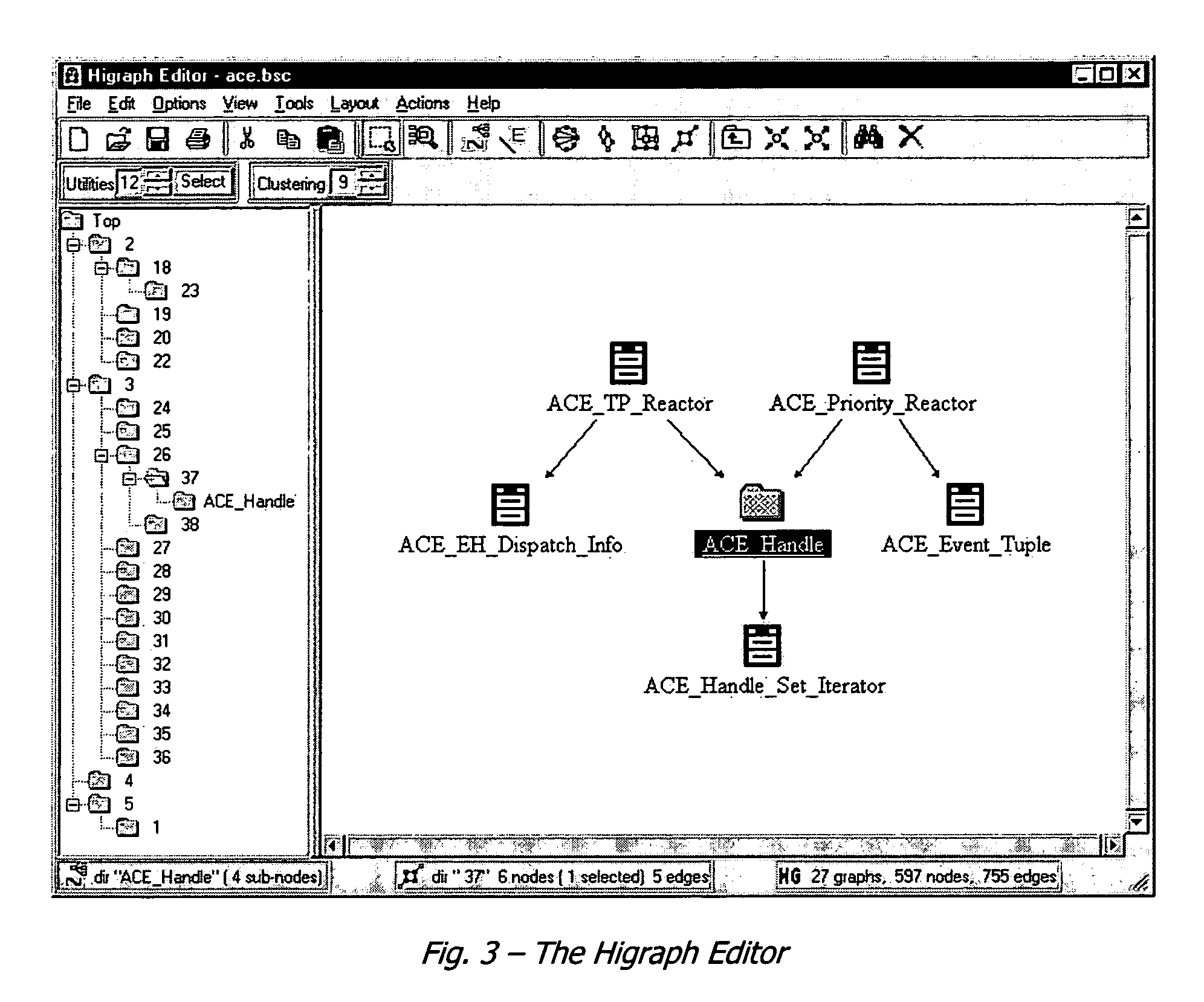
[0127]The system may be implemented using any of several commercially available graphing libraries that support the rendering of directed graphs. One preferred product is the Graphical Editor Toolkit (GET) from Tom Sawyer Software. GET includes facilities for causing a directed graph to be displayed in a number of different layouts, specifically hierarchical, circular, orthogonal and symmetric.

[0128]The present system renders hinodes using GET by traversing the HiNode objects within the HiGraph object representing the higraph to be rendered, and using the information derived thereby to instantiate tsNode objects in the GET library. GET uses tsNode objects to display nodes of a graph. In general, there is a one-to-one correspondence between the rendered Hinodes of a Higraph and the tsNode objects in the Tom Sawyer library. Likewise, there is a correspondence between rendered Hiedges and tsEdge objects. tsLables are associated with the tsEdges to indicate the “depth”. The specific nod...


PUM


Abstract

The present invention is directed to a system and methods for analyzing dependencies. The dependencies that may be analyzed include, for example, dependencies among methods or procedures in software source code, or in system configuration or deployment. A layered system is provided, comprising a back-end layer, abstraction layer and user interface layer are used to derive dependency information from third-party tools, and present the information through uniform interfaces to a user-interface layer. The system maintains a dependency model as a hierarchical graph structure in computer memory, and provides a plurality of user views which may be manipulated actively or passively by the user. Active manipulations are propogated through the back-end layer to modify the system analyzed, and passive manipulations affect the user views without changing the analyzed system. The system provides advantages to users seeking to understand complex systems with many dependencies.

Description

FIELD OF THE INVENTION[0001]The present invention is directed to methods and systems for computer-aided dependency analysis and design. In one aspect, the invention relates to analysis of software such as C++ code.BACKGROUND OF THE INVENTION[0002]One of the major problems in software development and maintenance is that of keeping track of the structure of the code so that changes may be made and, more generally, that the operation of the software may be understood.[0003]Very often, too few developers know a particular application's source code and it's vagaries sufficiently well to be able to make changes quickly. The code itself is either poorly structured and / or documented, usually as a result of being rushed into production, or because the code has been patched or layered too often without sufficient consideration. Even when code is properly structured and documented it can be equally difficult for someone to appreciate this fact without weeks of research. Before ever a line of c...

Claims


Application Information

Patent Timeline
Patent Type & Authority Patents(United States)
IPC IPC(8): G06F9/45G06F9/44
CPCG06F8/75G06F8/71
Inventor CHEDGEY, CHRISTOPHERO'REILLY, BRENDAN
Owner HEADWAY RES
Why Eureka
Try Eureka