Systems and methods for managing distributed database resources

a database resource and distributed database technology, applied in the field of relational database management systems and applications, can solve the problems of limited capacity for handling a very large number of data queries or transactions, limited dbms capacity increase returns for companies, and complex implementation, so as to reduce costs, expand the capacity of database resources, and avoid loss of quality or availability.

Active Publication Date: 2007-01-09
GOPIVOTAL
View PDF7 Cites 76 Cited by
  • Summary
  • Abstract
  • Description
  • Claims
  • Application Information

AI Technical Summary

Benefits of technology

[0014]The present invention provides application developers with the important feature of transparency of the underlying database architecture. That is, an application program can take advantage of the benefits of load balancing and fault tolerance without the necessity for architecture-specific software coding.
[0015]It is an object of the present invention is to extend the functionality of centralized database applications to the edge of the Internet, increasing quality while reducing costs.
[0016]It is another object of the present invention to expand the capacity of database resources without risk of losing quality or availability when more users or new geographic locations are added.
[0017]It is another object of the present invention to transparently extend a centralized DBMS server providing fault tolerance and load balancing benefits without the need for specialized programming or knowledge of the underlying network architecture by users and developers.

Problems solved by technology

A problem with such centralized DBMSs is the limited capacity for handling a very large number of data queries or transactions.
However, even with enormous capital investments in advanced hardware, a company will see limited returns in terms of increased DBMS capacity.
Although the concept of splitting the DBMS across multiple systems is simple, implementation has proved to be very complex.
This complexity is realized in the form of additional systems management and programming effort.
Even with this increased investment and complexity, it is widely known by system architects that most DBMS system cannot adequately be scaled beyond two coupled systems.
Accordingly, database replication has enjoyed only a limited degree of success, despite significant investments by DBMS manufactures and decades of aggressive competition.

Method used


Image

  • Systems and methods for managing distributed database resources
  • Systems and methods for managing distributed database resources
  • Systems and methods for managing distributed database resources

Examples


Embodiment Construction

[0029]FIG. 3A is a schematic diagram of an embodiment of the present invention.

[0030]System 300, in an embodiment, includes a computer 310 of a user. Computer 310 can include a processor 311 coupled via bus 313 to network port 315 and memory 317. Processor 311 can be, for example, an Intel Pentium® 4 processor, manufactured by Intel Corp. of Santa Clara, Calif. As another example, processor 311 can be an Application Specific Integrated Circuit (ASIC). An example of bus 313 is a peripheral component interconnect (“PCI”) local bus, which is a high performance bus for interconnecting chips (e.g., motherboard chips, mainboard chips, etc.), expansion boards, processor / memory subsystems, and so on.

[0031]Network port 315 can be an Ethernet port, a serial port, a parallel port, a Universal Serial Bus (“USB”) port, an Institute of Electrical and Electronics Engineers, Inc. (“IEEE”) 1394 port, a Small Computer Systems Interface (“SCSI”) port, a Personal Computer Memory Card International Asso...


PUM


Abstract

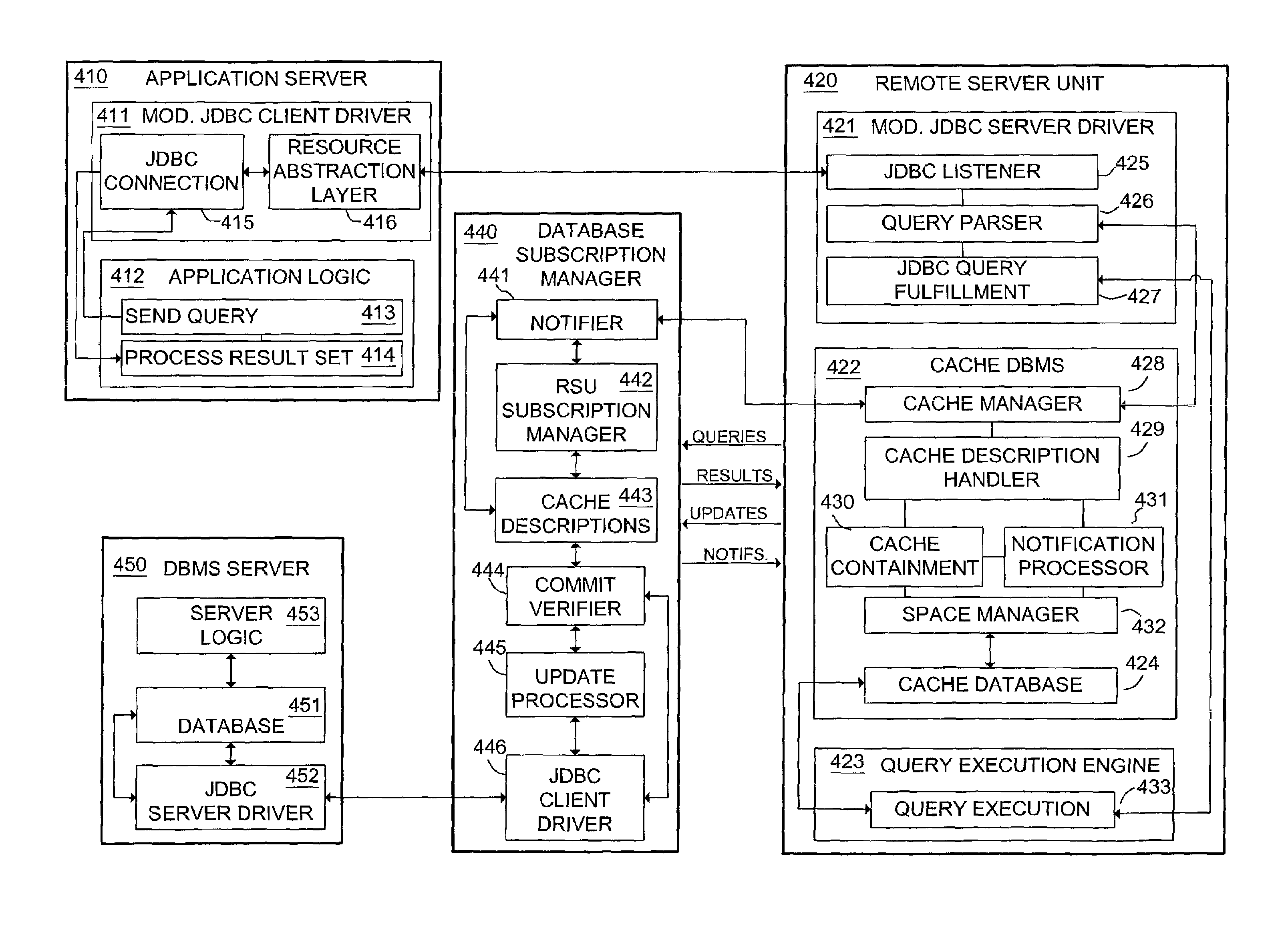
A system and method are described for implementing a distributed database caching system with the capability to support and accelerate read and update transactions to and from one or more central Database Management System (DBMS) servers for multiple concurrent users. The system and method include a resource abstraction layer in a database client driver in communication with remote server units (RSUs) having a cache database. RSUs respond to user requests using the cache database if possible. If the cache database does not have the needed data, the RSU sends the request to a database subscription manager (DSM) in communication with the DBMS server. The DSM responds to the request and sends predicate data based on queries processed by the DBMS server for use in updating the cache databases.

Description

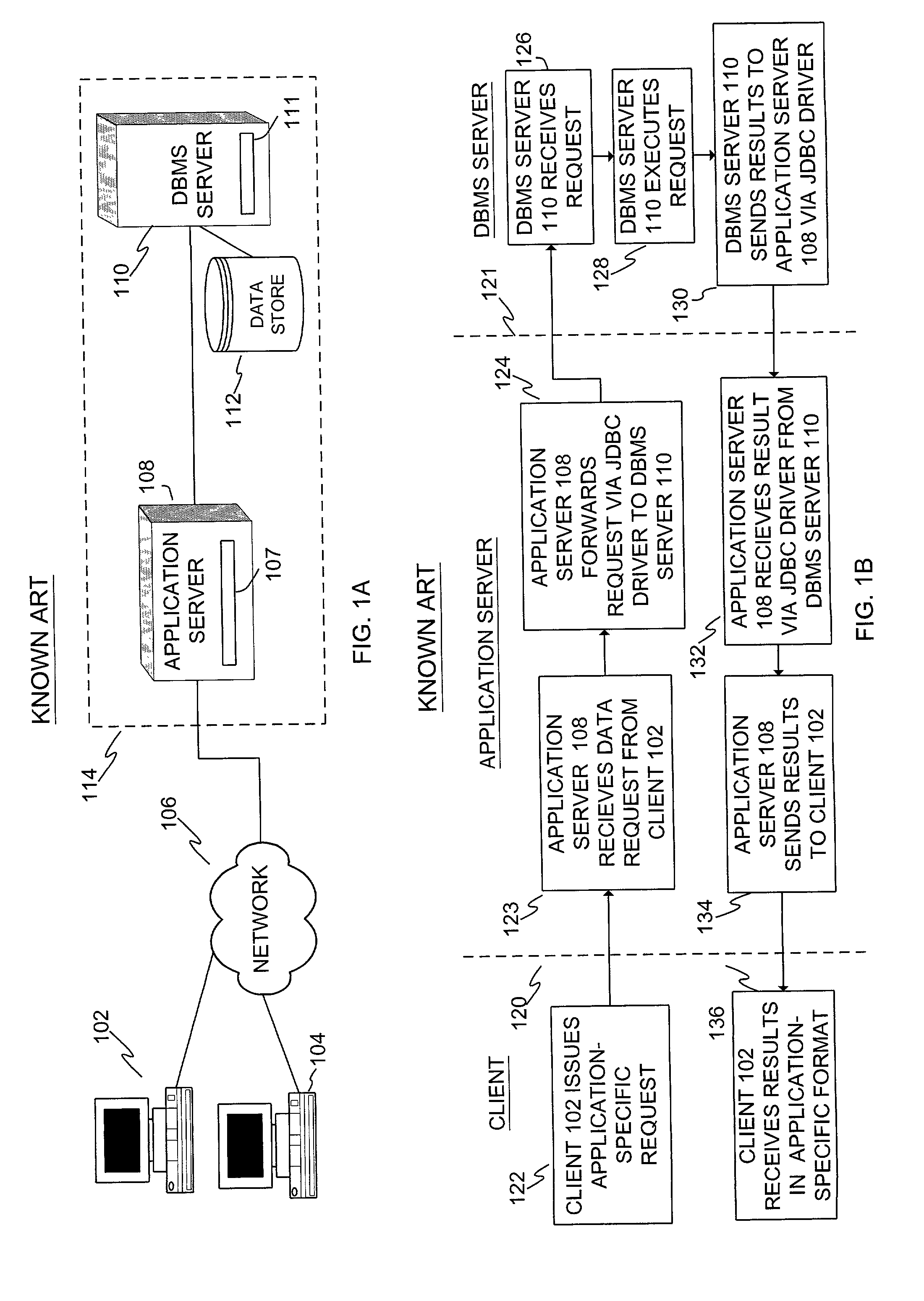
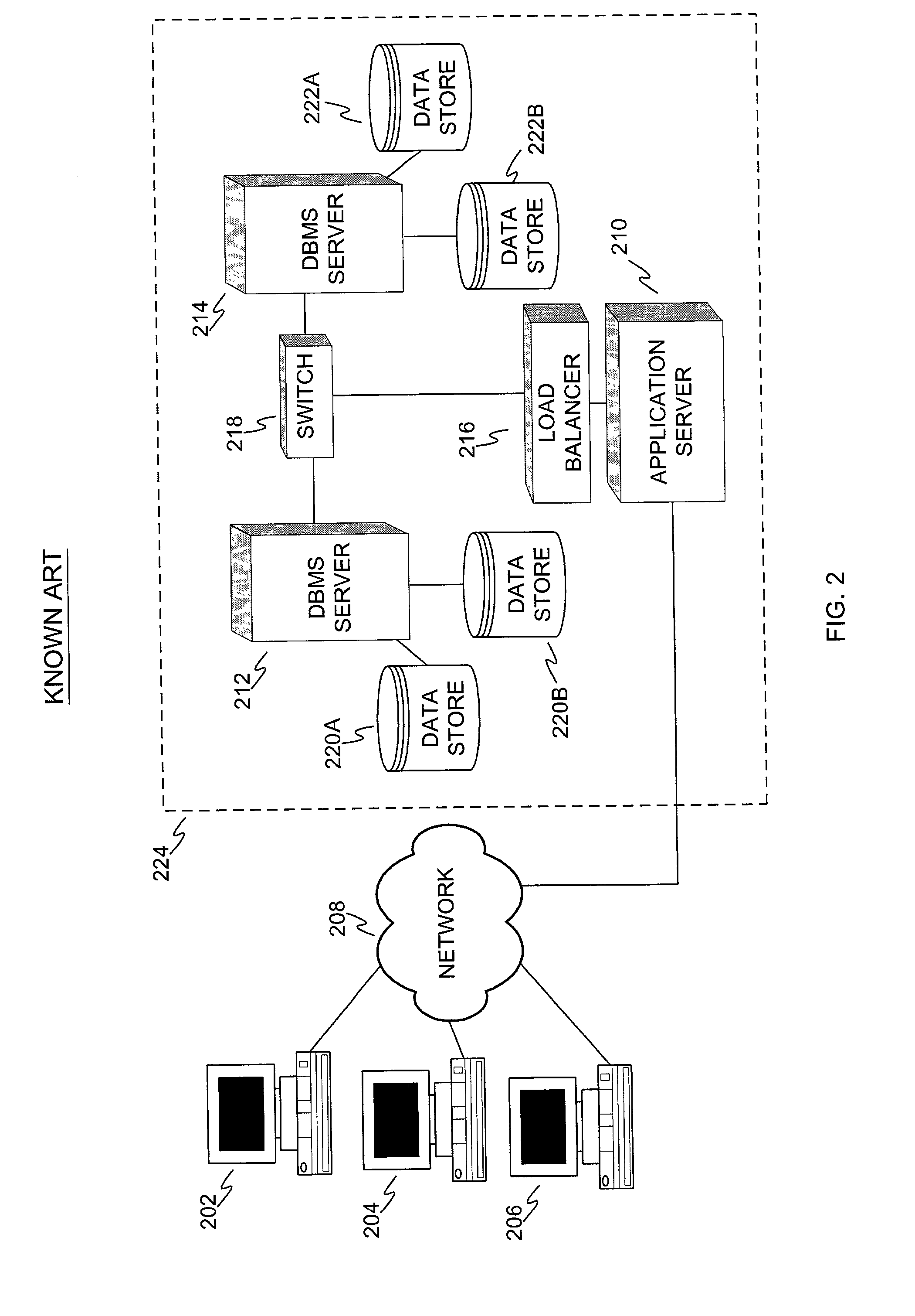
BACKGROUND[0001]This application claims the benefit of U.S. Provisional Application No. 60 / 270,126, filed Feb. 22, 2001, which is herein incorporated by reference in its entirety.FIELD OF THE INVENTION[0002]The present invention relates generally to relational database management systems and applications using such systems. More particularly the present invention relates to improved performance, redundancy and capacity of distributed database systems and applications.BACKGROUND OF THE INVENTION[0003]Conventional client / server distributed systems provide a centralized data storage and access facility, also referred to herein as a database management system (“DBMS”), for managing information in response to data queries and update transactions. As used herein, the terms “data query” or “query” mean read-only requests for data and the terms “update transaction” or “transaction” mean any read-write operations involving changes to the data stored in the database. A conventional client / ser...

Claims


Application Information

Patent Timeline
Patent Type & Authority Patents(United States)
IPC IPC(8): G06F7/00G06F15/16G06F17/30H04L29/06H04L29/08
CPCH04L29/06H04L67/2804H04L67/1008H04L67/2895H04L67/1021H04L67/2852H04L67/1023H04L67/288H04L2029/06054Y10S707/99933H04L67/1002H04L69/329H04L67/1034H04L67/10015H04L67/1001H04L67/561H04L67/5682H04L9/40
Inventor ESHLEMAN, JOHNJOHNSON, CLIFFORD W.LONERGAN, LUKE
Owner GOPIVOTAL
Why Eureka
Try Eureka