Compressor in the induction tract of an internal combustion engine

a technology of compressor and induction tract, which is applied in the direction of reaction engines, machines/engines, liquid fuel engines, etc., can solve the problem that the energy of exhaust gas is insufficient to keep the supercharger speed at a high level, and achieve the effect of increasing swirl and high flow velocity

Inactive Publication Date: 2008-08-19
DAIMLER AG
View PDF21 Cites 13 Cited by
  • Summary
  • Abstract
  • Description
  • Claims
  • Application Information

AI Technical Summary

Benefits of technology

[0006]Depending on the operating conditions of the internal combustion engine, the swirl structures can be adjusted to different relative positions, thereby altering the flow volumes and direction of the combustion air supplied to the compressor wheel. Thus the swirl device, particularly at low loads and rotational speeds, can be brought into a position which reduces the flow cross section by the two individual swirl structures as they are inserted into the flow cross section or brought into a position in which the guide vanes of both swivel structures lie directly adjacent to one another or, viewed over the periphery, engage in one another. The combustion air can flow through the remaining flow channels between adjacent guide vanes and, in so doing, can undergo a swirl, which, when the compressor wheel blades are struck, imparts a driving momentum to the compressor wheel, so that the compressor wheel can be kept at an increased rotational speed level, even at very low loads and speeds of the internal combustion engine.
[0012]Additionally or alternatively to a positioning of the guide vanes of a swirl device in the intermediate spacing between adjacent guide vanes of the other swirl structure, it may also be expedient for the guide vanes of one swirl structure to be positioned on the end face of the guide vanes of the other swirl structure. This provides for a lengthening of the guide vanes, whereby an enhanced swirl can be obtained. Through the interaction of the guide vanes of the two swirl structures, a Laval nozzle channel can be formed in the space between adjacent guide vanes, whereby high flow velocities and even a supersonic flow of the combustion air flowing therethrough can be obtained.

Problems solved by technology

At low loads and speeds of the internal combustion engine, the energy of the exhaust gas is insufficient to keep the supercharger speed at a high level.

Method used


Image

  • Compressor in the induction tract of an internal combustion engine
  • Compressor in the induction tract of an internal combustion engine
  • Compressor in the induction tract of an internal combustion engine

Examples


Embodiment Construction

[0020]In the figures, identical components are provided with identical reference symbols.

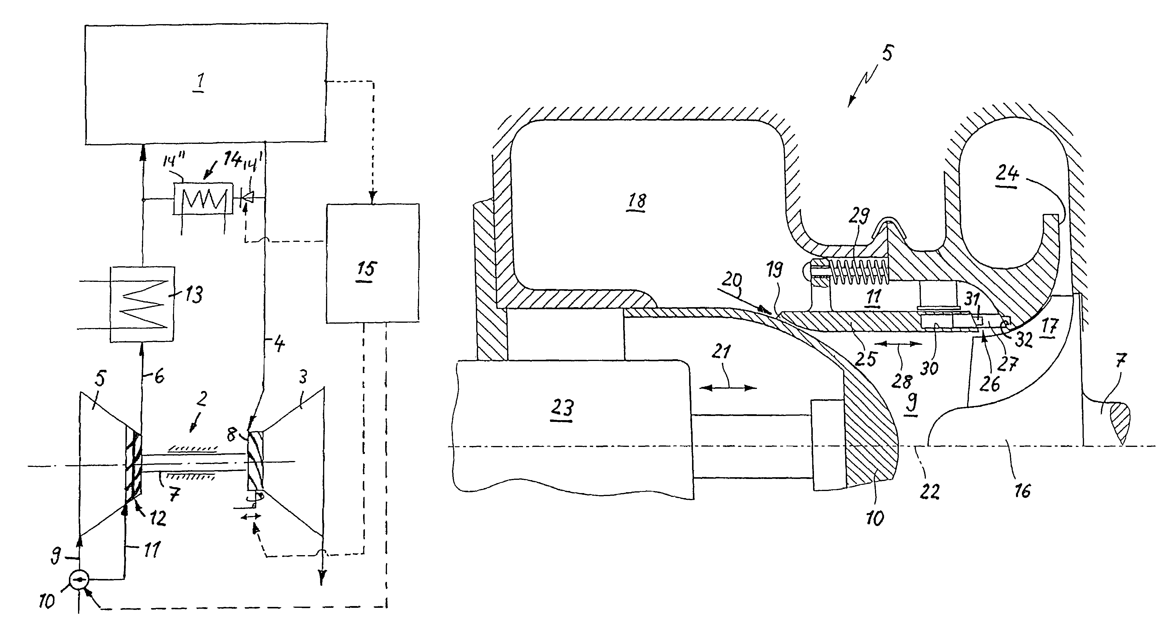
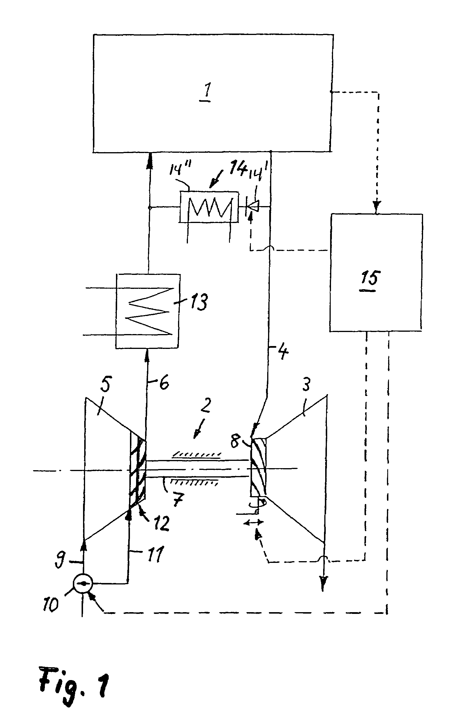
[0021]The internal combustion engine 1 represented in FIG. 1-a gasoline engine or a diesel engine includes an exhaust gas turbocharger 2 having an exhaust gas turbine 3 disposed in the exhaust gas system 4 and a compressor 5 disposed in the induction tract 6. A turbine wheel of the exhaust gas turbine 3 is driven by the exhaust gases of the internal combustion engine, which exhaust gases are under exhaust gas backpressure, the turbine wheel rotation being transmitted by a shaft 7 to a compressor wheel in the compressor, whereupon combustion air is sucked from the environment and compressed to an increased boost pressure. The exhaust gas turbine 3 is provided with a variable turbine geometry 8 for the adjustment of the effective turbine entry cross section. The compressor 5 has in a compressor inlet duct 9 an adjustable blocking member 10, by which the quantity of combustion air to be supplied ca...


PUM


Abstract

In a compressor in the induction tract of an internal combustion engine with a compressor by which combustion air can be compressed to an increased boost pressure and which includes a compressor wheel rotatably mounted in a compressor housing with a main inlet duct in the flow path to the compressor wheel, and an auxiliary inlet duct joining the main inlet duct in the area of the compressor wheel, an adjustable swirl device is provided in the auxiliary intake duct, which comprises two separate, interacting swirl structures with a plurality of guide vanes distributed over the periphery and arranged so that the flow cross-section between the guide vanes of the two swirl structures can be changed by an adjusting motion of at least one swirl structure, the vane height of the guide vanes of the smaller swirl structure being 5% to 35% of the vane height of the guide vanes of the larger swirl structure.

Description

[0001]This is a Continuation-In-Part Application of International Application PCT / EP2004 / 006836 filed Jun. 24, 2004 and claiming the priority of German application 103 29 281.0 filed Jun. 30, 2003.BACKGROUND OF THE INVENTION[0002]The invention relates to an intake air compressor for an internal combustion engine including a compressor wheel disposed in the air intake duct and an adjustable inlet guide vane structure for controlling the airflow to the compressor.[0003]DE 199 55 508 C1 discloses an exhaust gas turbocharger for an internal combustion engine, which comprises an exhaust gas turbine in the exhaust gas duct and a compressor in the air intake duct of the internal combustion engine. The exhaust gas turbine is driven by the pressurized exhaust gases of the engine, the rotation of the turbine wheel being transmitted by a shaft to the compressor wheel, which compresses combustion air sucked from the environment to an increased boost pressure, at which the combustion air is fed ...

Claims


Application Information

Patent Timeline
Patent Type & Authority Patents(United States)
IPC IPC(8): F02B33/44F01D17/14F01D17/16F02B37/22F02B37/24F04D27/00F02D9/02
CPCF02B37/225F02B37/24Y02T10/144F02D2009/0283Y02T10/12
Inventor SUMSER, SIEGFRIED
Owner DAIMLER AG
Why Eureka
Try Eureka