Concealed camera

a camera and lens body technology, applied in the field of concealed cameras, can solve the problems of insufficiently addressing the above-delineated concerns or needs, affecting the performance of commercial and industrial vehicles, and being susceptible to damage,

Inactive Publication Date: 2008-08-19
SILVERSTATE SAFETY IMAGE
View PDF7 Cites 41 Cited by
  • Summary
  • Abstract
  • Description
  • Claims
  • Application Information

AI Technical Summary

Benefits of technology

[0010]Yet another object of the present invention is to provide a concealed camera wherein the lens views the image through a pinhole of such small size that the camera is undetectable. Despite the small diameter peep hole, the high resolution of the camera along with its distinctly shaped lens permits a wide angular field of vision, similar to that of a more open view as would be perceived by a conventional camera.
[0011]The objects of this invention are accomplished by incorporating a sub miniature camera within an housing having numerous outward appearances, none of which would be perceived by a passer by as a camera or surveillance device. Moreover, in so positioning the device, it is dependent upon only the ambient light and environmental conditions and in everyday surroundings, the present invention will provide a clear and sharp image to a recipient screen or other device. Since the subminiature camera itself is the only critical element to be enclosed within the housing, the size and shape of the housing may be greatly reduced and may be fully customized to the needs or particular aesthetic or functional design requirements of the user. In addition, the positioning of the mounted camera, for example on a vehicle, is greatly simplified, as the camera may be mounted on any external surface of the housing and will thereafter span a wide field of vision.

Problems solved by technology

Additionally, in a motor vehicle, especially a heavy vehicle such as a tractor trailer or a garbage truck, concerns include vandalism, traffic safety and overcoming obscured or blind spots during normal operation and backing up the vehicle.
These mirrors, due to both their size and location, however, are susceptible to damage, wind resistance, wind noise and other driver distractions.
Many commercial and industrial vehicles presently perform complicated and / or multiple tasks.
To date, none of the above delineated concerns or needs have been adequately addressed.
As such, these cameras are highly susceptible to damage from inclement weather, scrapes on the side of the vehicle as well as falling road debris.
In addition, any bumping of the camera or its mounting will likely disturb the field of vision of the camera, rendering it useless for the proposed task.
In addition, such a large system, when used for security purposes, is often counterproductive, as it alerts would be thieves of an important cargo.
Conventional camera systems are also typically visually undesirable.
Large systems, as discussed above, are obtrusive and become targets for malcontents and criminals.
Moreover, should the subject realize they are under surveillance they may either become uncomfortable and exit the premises or vehicle.
Alternatively, if surveillance is perceived, the subject, whether they are an outside individual or even an employee, may take action to end the operation of the device, such as disconnection of power or damage to the camera.
Lastly, conventional cameras may distract from the aesthetic appeal of the interior or exterior of the premises or vehicle on which they are mounted.
That system, however, is highly deficient for the above described needs.
This would preclude its use without a light source and in some positions on a vehicle, the light may actually draw unwanted attention to the camera assembly.
Similarly, having to view the image through a colored lens will necessarily distort or artificially color the image.
Moreover, the colored lens will detract from and may even preclude the reception of a clear image, especially at night or in darkened conditions.
Also, the Steed system does not describe nor contemplate the use of multiple synchronized cameras for different operations of a vehicle and the desirable automatic synchronization of the multiple cameras, other than a reliance upon the turn signal indicator elements which must be engaged by the operator.

Method used


Image

  • Concealed camera
  • Concealed camera
  • Concealed camera

Examples


Embodiment Construction

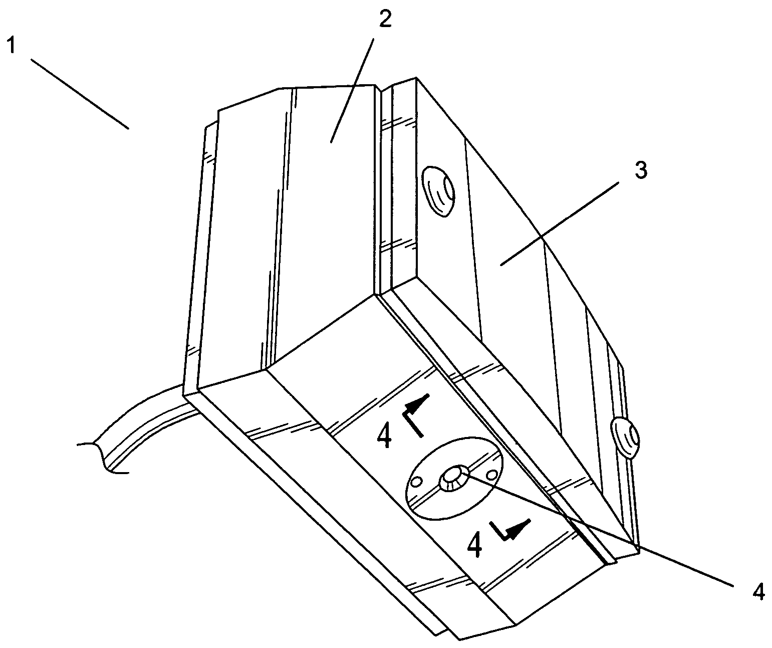
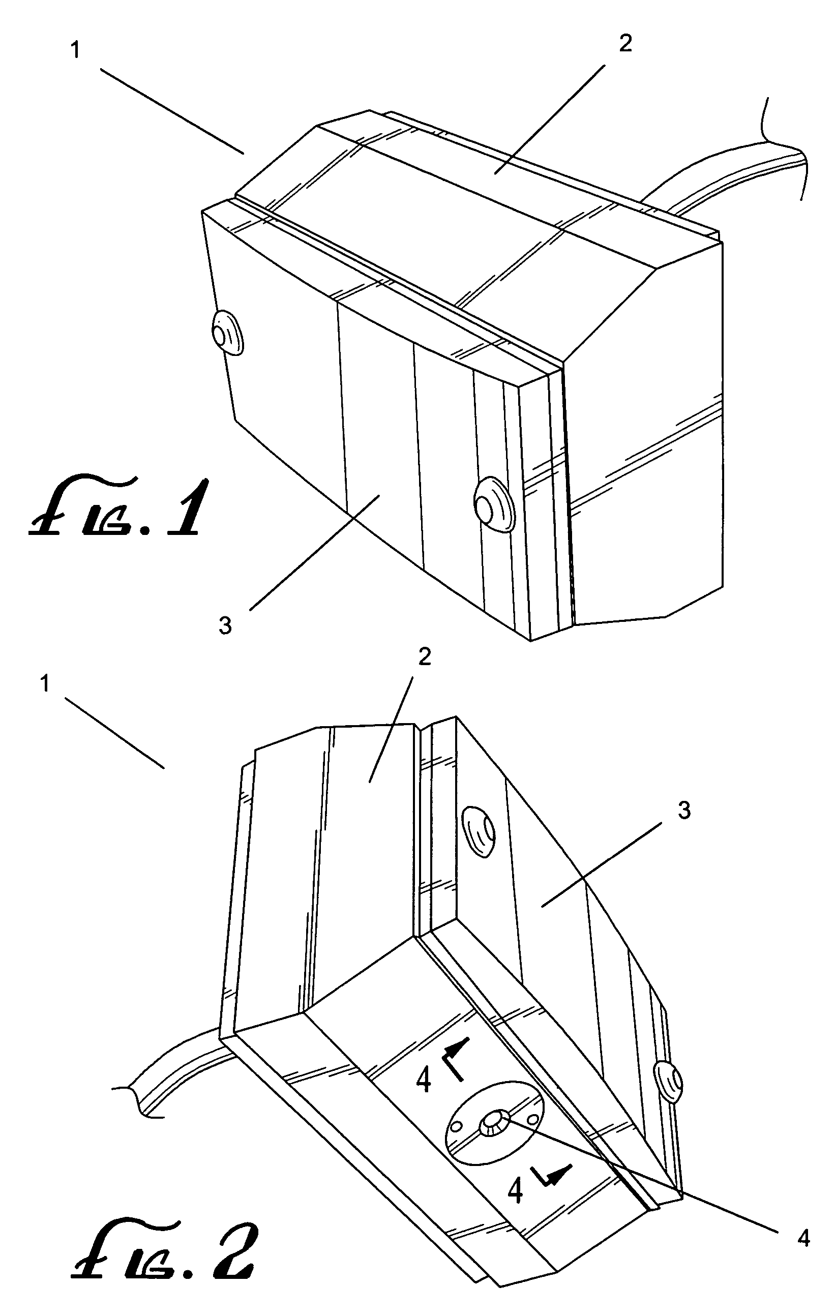
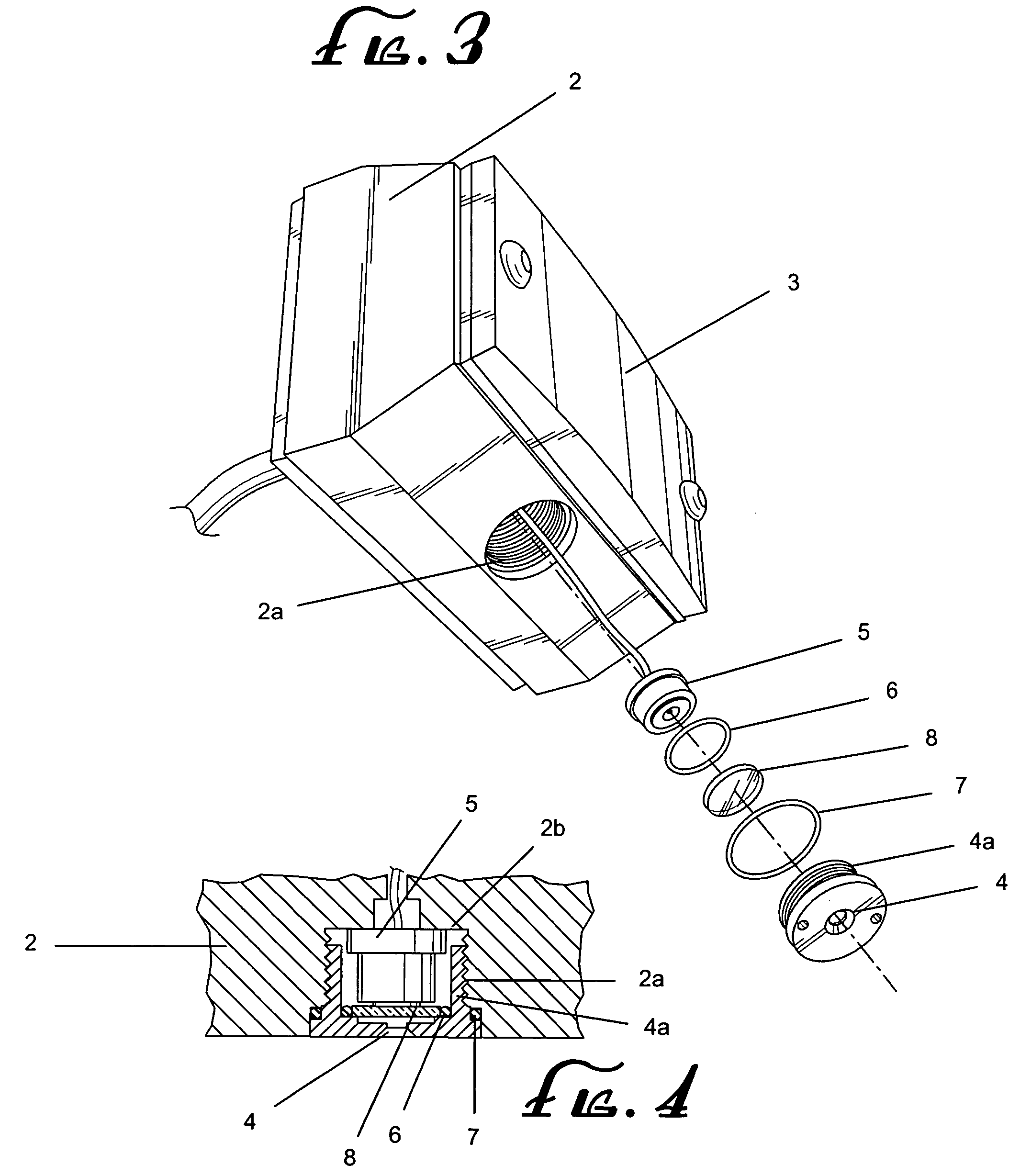
[0020]The accompanying Figures depict embodiments of the present invention, and features and components thereof. With regard to means for fastening, mounting, attaching or connecting the components of the present invention to form the apparatus as a whole, unless specifically described otherwise, such means are intended to at least encompass conventional fasteners such as machine screws, machine threads, snap rings, hose clamps such as screw clamps and the like, rivets, nuts and bolts, toggles, pins and the like. Components may also be connected by friction fitting, snap fitting, adhesives, or by welding or deformation, if appropriate. Unless specifically otherwise disclosed or taught, materials for making components of the present invention are selected from appropriate materials such as metal, metallic alloys, natural or synthetic fibers, plastics and the like, and appropriate manufacturing or production methods including casting, extruding, molding and machining may be used.

[0021...


PUM


Abstract

A concealed camera comprising a housing, a subminiature camera and a peep hole of very small size through which the camera may perceive a large field of vision. With a high resolution camera and the tiny peep hole, the camera may be positioned or located in plain view as concealed within a myriad of functional objects, such as a clock, reflector, light or any other common looking device in the area of desired view or surveillance. Multiple concealed cameras may by employed and perhaps synchronized in a surveillance system such that the downstream viewed image may be automatically switched from one image to another as desired by the system user.

Description

FIELD OF INVENTION[0001]The present invention is directed to the use of a camera for safety, surveillance or a host of different uses. More specifically, the present invention is directed to the use of a concealed camera whereby it is mounted in an housing which would typically be mistaken for a common functional device. The invention may be used in almost any situation, whether industrial, commercial or residential. In addition, the invention may be used in conjunction with a building, vehicle or any other setting where safety, visibility or security concerns arise.BACKGROUND OF THE INVENTION[0002]For safety and security reasons, these is a need for a versatile camera system which may be used for surveillance without detection. In a commercial or residential setting, these applications are both numerous and obvious. In an outside location, such as a loading dock, such a system is needed for security and safety of the personnel, vehicles and the goods involved. Additionally, in a mo...

Claims


Application Information

Patent Timeline
Patent Type & Authority Patents(United States)
IPC IPC(8): G03B17/00
CPCG08B15/001G08B13/19619
Inventor BADALIAN, EDWARD
Owner SILVERSTATE SAFETY IMAGE
Why Eureka
Try Eureka