Light diffuser used in a testing apparatus

a technology of light diffuser and testing apparatus, which is applied in the direction of biomass after-treatment, instruments, and handling using diaphragms/collimeters, etc., can solve the problems of difficult to reproduce measurement results with good precision, and sensor intensity drift effect, non-uniform intensity drift across the sensor face, and the effect of intensity dri

Inactive Publication Date: 2008-08-19
EPPENDORF AG
View PDF25 Cites 63 Cited by
  • Summary
  • Abstract
  • Description
  • Claims
  • Application Information

AI Technical Summary

Benefits of technology

[0005]An apparatus for photometrically testing several specimens, each irradiated by a light source, and the light altered by the specimens being detected by an optical device, is provided. The apparatus includes plurality of light sources (each associated with a specimen) or only a single light source, a plurality of sample holders or wells configured adjacent to one another on a support (preferably a thermocycler), a detector that receives altered light from sample within the sample holders, a filter for eliminating interfering light, and a sensor having a sensor face. The detector also includes a light diffusing member (light diffuser), wherein light from a sample is diffused and shines on a greater portion of the sensor face surface as compared to when the light is not diffused.
[0006]The filter eliminating interfering light (wavelength filter) is situated in front of the sensor. As regards fluorescence measurements, the filter is a long wavelength filter eliminating residual short wavelength portions of the excitation light illustratively arising as scattered light from the light sources. Bandpass filters are also appropriate for these purposes.
[0008]As a result of the diffusing optical member, a sample light beam is placed on a larger percentage of the area of the sensor face and more homogeneous illumination of the sensor is provided. The effects of intensity drift, non-uniform sensitivity across the face of the sensor, and non-uniform intensity drift across the face of the sensor are significantly reduced.

Problems solved by technology

Additionally, the sensor is subject to the effect of intensity drift over time.
As a result of these three factors, when the position on the sensor where light from the sample shines changes, measurement results can be difficult to reproduce with good precision.
Additionally, if the brightness of the light is not consistent across the section of the sensor upon which the light shines, measurement results are difficult to reproduce.
This is a time consuming process and also cannot be used for correcting intensity drift.

Method used


Image

  • Light diffuser used in a testing apparatus
  • Light diffuser used in a testing apparatus
  • Light diffuser used in a testing apparatus

Examples


Embodiment Construction

[0014]The specification of U.S. Pat. No. 7,102,131 to Spolaczyk et al., which issued on Sep. 5, 2006, is hereby incorporated in its entirety by reference.

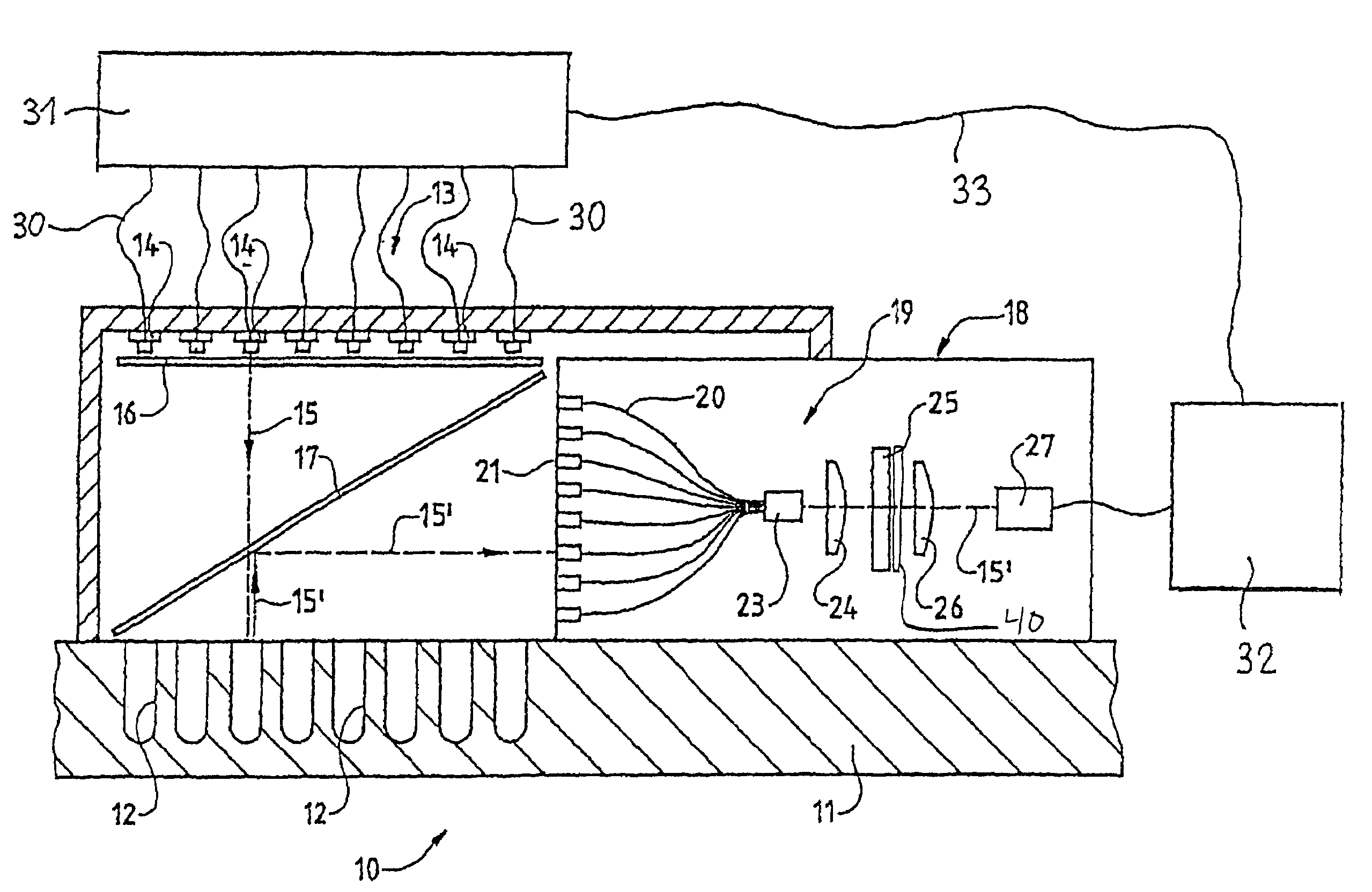
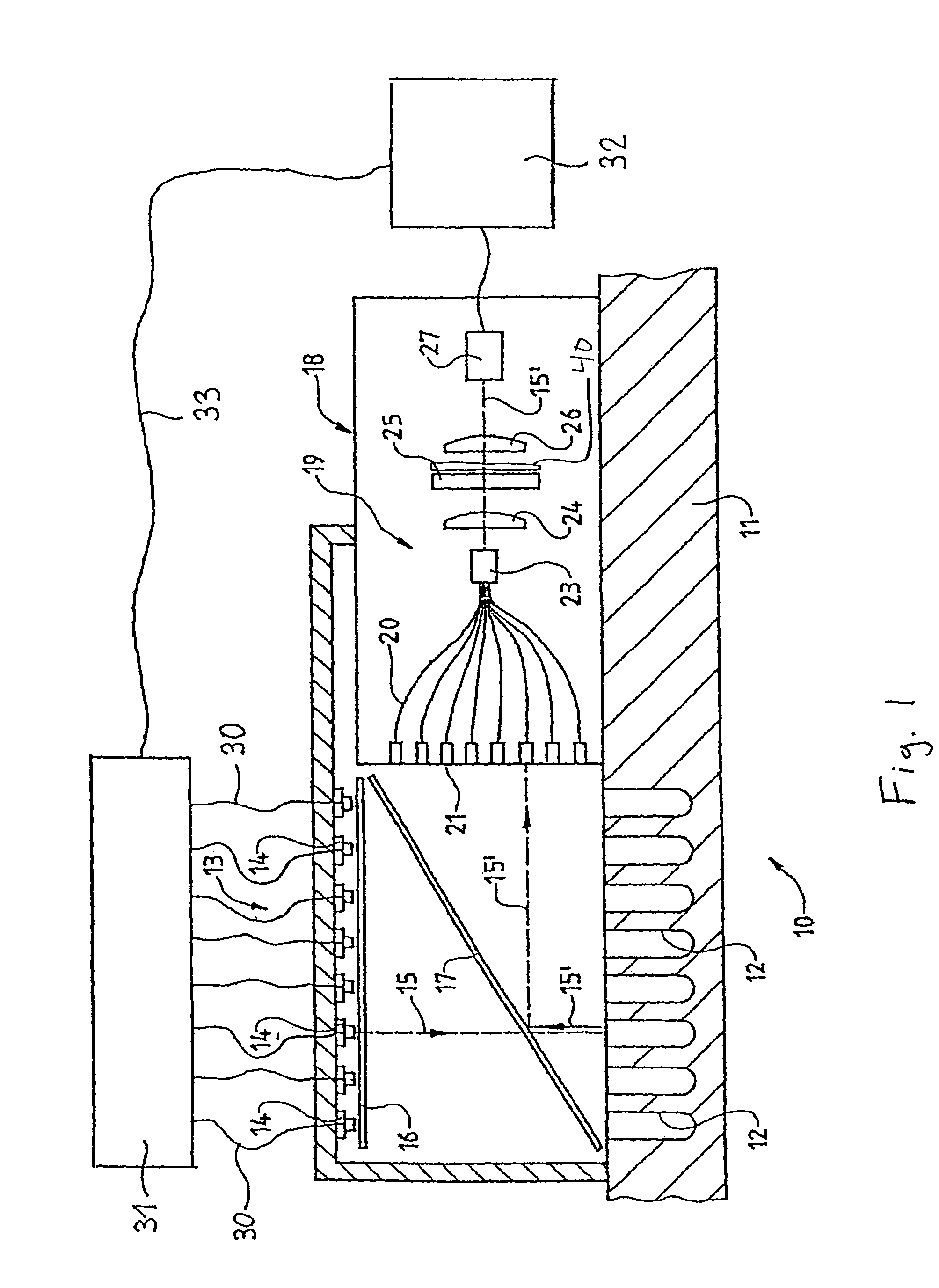
[0015]Referring to FIG. 1, the apparatus 10 comprises a schematic, conventional thermocycler 11 with wells 12. Reaction vials (not shown) are in place in the wells 12. Each vial contains one sample with one or more fluorescence indicators.

[0016]A covered housing 13 fitted with an illumination unit of several LEDs 14 is set on the thermocycler 11. One LED 14 is allocated to each well 12. Preferably, the LEDs 14 are configured as an array. Each LED 14 points in a direction such that it will irradiate only one associated well 12 and, if possible at all, not the adjacent wells. The LEDs 14 may, in particular, be laser diodes. The LEDs 14 are connected by cables 30 to a control unit 31 which is in turn connected by a cable 33 to an analyzer 32. Alternatively, a single source of light may be used.

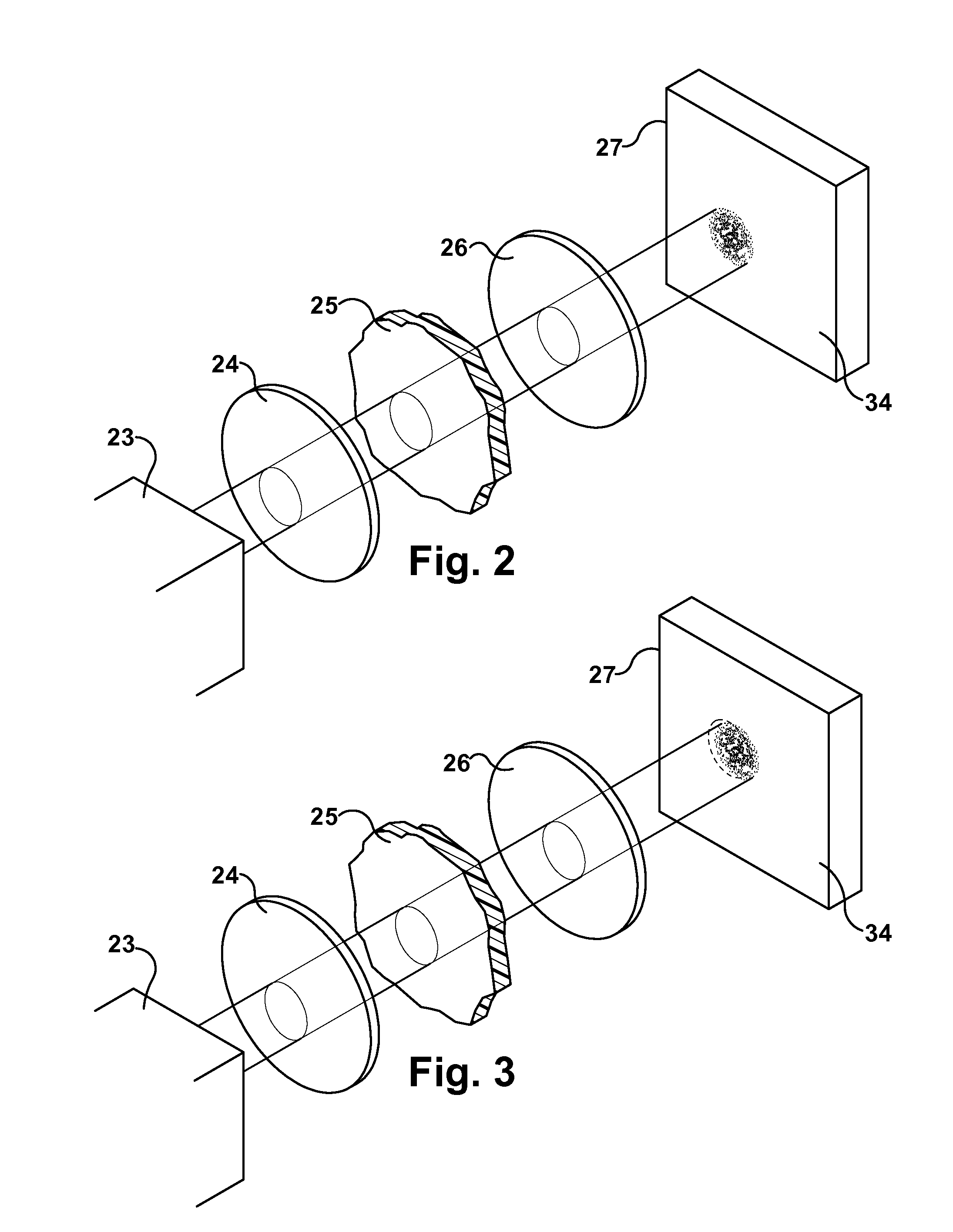
[0017]An illustrative light path is denot...


PUM

PropertyMeasurementUnit
thicknessaaaaaaaaaa
optical deviceaaaaaaaaaa
brightnessaaaaaaaaaa

Abstract

An apparatus for photometrically testing several specimens each irradiated by a light source, the light altered by the specimens being detected by an optical device and analyzed, the apparatus including a light source, a plurality of sample holders configured adjacent to one another on a support, a detector that receives altered light from sample within the sample holders, the detector including a filter for eliminating interfering light, a sensor having a sensor face and a diffusing optical member located between the filter and the sensor, wherein light is diffused and shines on a greater portion of the sensor surface, and with a more homogeneous brightness as compared to when the light is not diffused.

Description

BACKGROUND OF THE INVENTION[0001]A device for the photometric measurement of samples is generally disclosed within U.S. Pat. No. 7,102,131 to Spolaczyk et al. Samples within individual sample wells are exposed to radiation from a single light source or a series of light sources and the light modified by the samples, for example fluorescence light, is intercepted by an optical device and is guided to a section of at least one sensor for measuring the intensity and evaluation thereof in an evaluation device arranged downstream of the sensor. The light source(s) are controlled individually by a control device, and the evaluation device and the control device are controlled such that the evaluation device can separate the light from each sample from the light of the other samples. The position of the sample upon, for example, a thermocycler that supports the sample determines the exact position where light modified by the samples shines on the sensor. Small shifts in the position of the...

Claims


Application Information

Patent Timeline
Patent Type & Authority Patents(United States)
IPC IPC(8): G01N21/27
CPCG01N21/6452G01N2021/6484
Inventor ECKERT, GERDTIMMANN, LUTZLAPCZYNA, MARKUSSCHAFRINSKI, ARNE
Owner EPPENDORF AG
Why Eureka
Try Eureka