Method for operating an internal combustion engine

a technology of internal combustion engine and combustion chamber, which is applied in the direction of electrical control, process and machine control, instruments, etc., can solve the problems of complex or inconvenient ascertainment of the air filling in the combustion chamber, the effect of engine fuel consumption and emissions, and the inability to control the temperature of the combustion chamber, etc., to achieve the effect of minimal sensor expense, low cost, and low cos

Active Publication Date: 2008-08-19
ROBERT BOSCH GMBH
View PDF10 Cites 21 Cited by
  • Summary
  • Abstract
  • Description
  • Claims
  • Application Information

AI Technical Summary

Benefits of technology

[0006]According to the invention, it has been recognized that in systems with major camshaft overlap, there is a nonlinear relationship between the air filling in a combustion chamber and the air pressure in the intake conduit. It has also been recognized that this nonlinear relationship is essentially a function of the ratio between the air pressure prevailing in the intake conduit and the ambient pressure. In the method of the invention, this ratio is therefore additionally used to ascertain the air filling present in the combustion chamber. This air filling can therefore be determined with high precision even in systems with major camshaft overlap, which in turn, above all when the engine operates in air-guided fashion, permits a precise setting of a desired fuel-air mixture in the combustion chamber. Finally, by the provisions of the invention, both engine fuel consumption and engine emissions are improved.
[0007]An advantageous refinement of the method of the invention is distinguished in that the model additionally receives as its input variable a temperature of the air present in the combustion chamber. As a result, mistakes based on an altered air density air averted or at least reduced, and the precision in ascertaining the air filling is improved still further.
[0008]In a refinement of this, it can be assumed that the temperature of the air present in the combustion chamber is equal to the detected temperature of the air in the intake conduit. This reduces the computation effort, without markedly worsening the precision in ascertaining the air filling.

Problems solved by technology

Correct metering of the fuel in turn has effects on engine fuel consumption and emissions.
However, it has been found that in such systems, if the camshaft overlap is great, the ascertainment of the air filling in the combustion chamber has so far been either complex or imprecise.

Method used


Image

  • Method for operating an internal combustion engine
  • Method for operating an internal combustion engine
  • Method for operating an internal combustion engine

Examples


Embodiment Construction

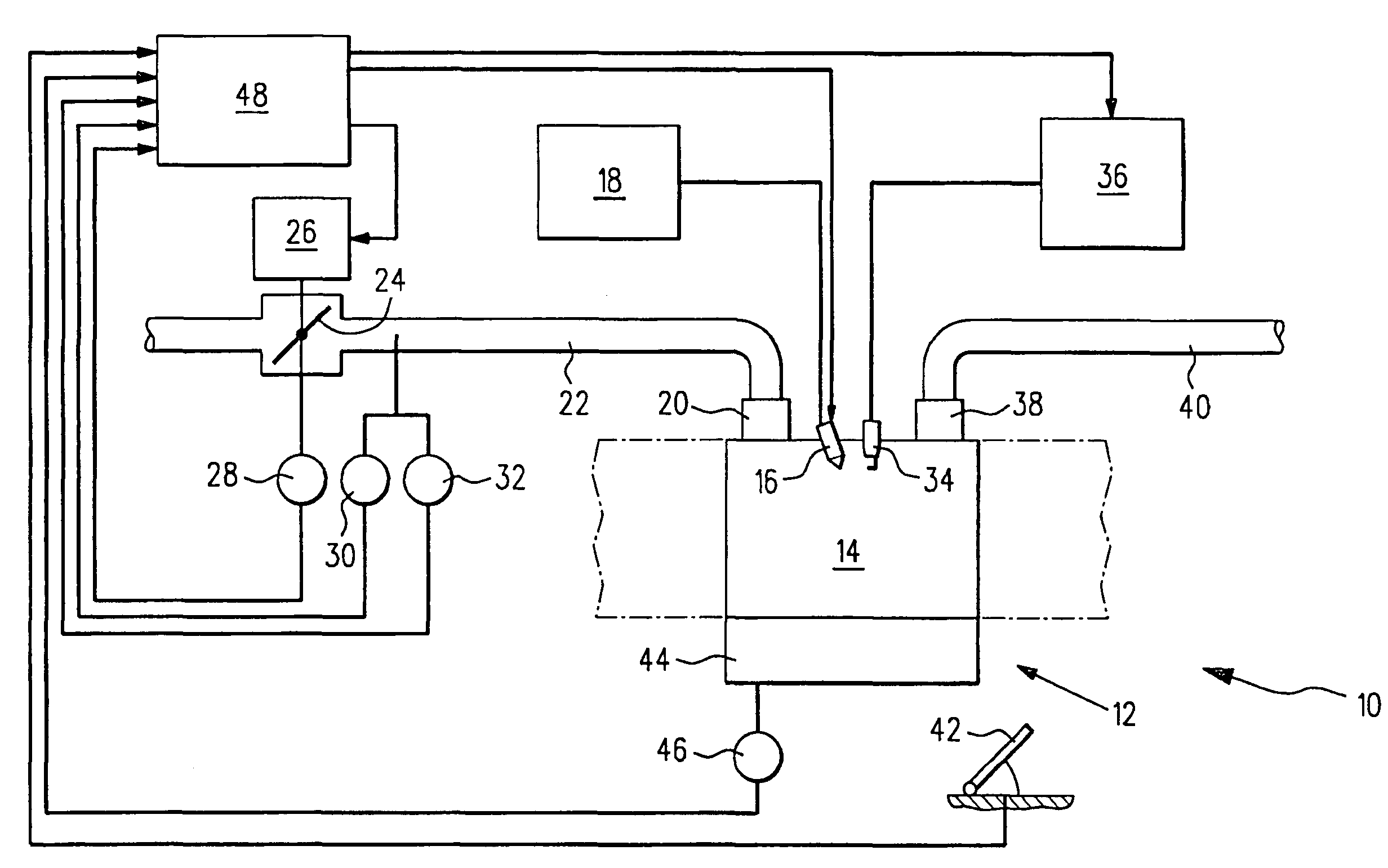
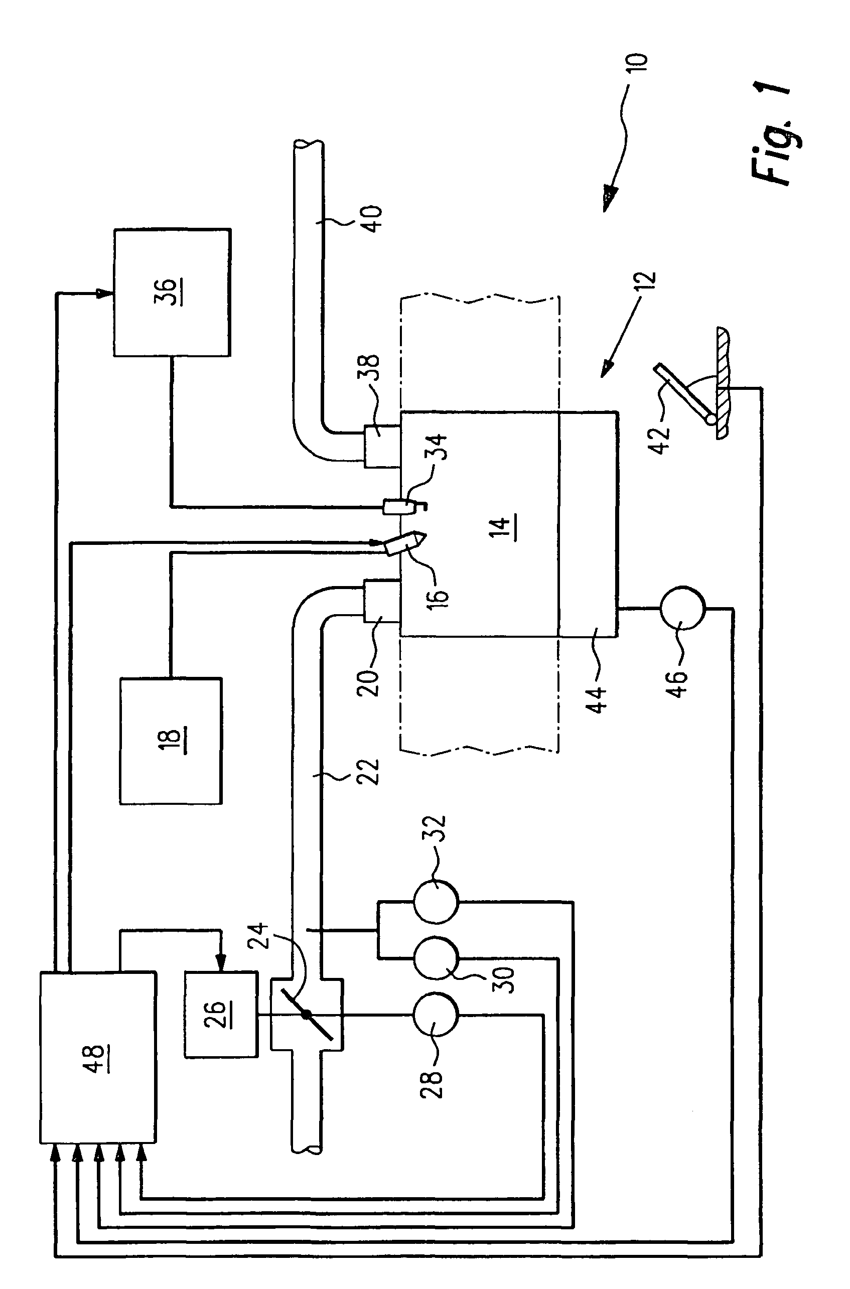
[0023]An internal combustion engine is identified overall in FIG. 1 by reference numeral 10. It includes a plurality of cylinders, of which for the sake of simplicity only one is shown in FIG. 1, at reference numeral 12. The corresponding combustion chamber is assigned reference numeral 14. Fuel is injected into the combustion chamber 14 directly by means of a fuel injector 16, which is connected to a fuel system 18. Air reaches the combustion chamber 14 via an inlet valve 20 and an intake conduit 22, in which conduit a throttle valve 24 is located. The throttle valve is adjusted by a control motor 26; its current position is detected by a throttle valve sensor 28. The air pressure prevailing in the intake conduit 22 is detected by a pressure sensor 30, and the corresponding temperature is detected by a temperature sensor 32 that is combined with the pressure sensor. The pressure sensor 30 is seated downstream of the throttle valve 24 and measures the pressure upstream of the inlet ...


PUM


Abstract

In operation of an internal combustion engine, an air filling (rl) in a combustion chamber is ascertained, taking into account a pressure (ps) in an intake conduit. It is proposed that the air filling (rl) be ascertained on the basis of a model (A), which as its input variables receives an rpm (nmot) of a crankshaft and a ratio of the pressure (ps) in the intake conduit (22) to an ambient pressure (pu).

Description

BACKGROUND OF THE INVENTION[0001]The invention relates to a method for operating an internal combustion engine, in which an air filling in a combustion chamber is ascertained taking into account a pressure in an intake conduit. The invention also relates to a computer program, an electrical memory for a control and / or regulating device of an internal combustion engine, and to control and / or regulating device of an internal combustion engine.[0002]A method of the type defined at the outset is known on the market. In many internal combustion engines, the pressure in an intake conduit is measured by means of a pressure sensor. Via a linear relationship, an air filling in the combustion chambers of the engine is calculated from the measured pressure. Above all in air-guided systems, knowledge of this air filling is important for correct metering of the fuel into the combustion chambers of the engine. Correct metering of the fuel in turn has effects on engine fuel consumption and emissio...

Claims


Application Information

Patent Timeline
Patent Type & Authority Patents(United States)
IPC IPC(8): G06F17/00F02D11/10G01M19/00G01M99/00
CPCF02D41/1401F02D41/18F02D2200/704F02D2200/0406F02D2200/0402
Inventor WILD, ERNST
Owner ROBERT BOSCH GMBH
Why Eureka
Try Eureka