Control method of wavelength dispersion compensator, and wavelength dispersion compensator

a wavelength dispersion compensator and control method technology, applied in multiplex communication, transmission monitoring, instruments, etc., can solve the problems of insertion loss characteristic in the transmission band the larger the error of the desired wavelength dispersion value, and the change of the vipa-type wavelength dispersion compensator

Inactive Publication Date: 2008-08-26
FUJITSU LTD
View PDF18 Cites 6 Cited by
  • Summary
  • Abstract
  • Description
  • Claims
  • Application Information

AI Technical Summary

Benefits of technology

[0010]The present invention has been accomplished in view of the above problems and has an object to provide a control technique for reducing the wavelength dependence of wavelength dispersion values in a wavelength dispersion compensator. Further, the present invention has an object to provide a control technique for suppressing a change in wavelength transmission characteristic with a variation of ambient temperature or a change in setting of wavelength dispersion value.
[0011]In order to achieve the above objects, the present invention provides a control method of a wavelength dispersion compensator which comprises: an optical component provided with a demultiplexing function, including a device having two reflective surfaces which are opposed and parallel to each other, in which a light condensed in the one-dimensional direction is incident between the reflective surfaces of the device, and a part of the incident light is transmitted through one of the reflective surfaces while the incident light being multiple-reflected on the respective reflective surfaces, to be emitted, and the emitted light interferes mutually, so that optical beams traveling directions of which are different from each other according to wavelengths are formed; and a reflector reflecting, at a previously set position, optical beams of respective wavelengths emitted from one of the reflective surfaces of the optical component in different directions to return the optical beams to the optical component, respectively. A first aspect of this control method comprises the following respective processes: (1) acquiring to store data relating to wavelength dispersion values in respective wavelengths in a wavelength band of the incident light so as to correspond to a position of the reflector, before starting the operation of wavelength dispersion compensation by the wavelength dispersion compensator; (2) inputting a setting condition inclusive of the wavelength dispersion values to be compensated at the operation time and wavelength information of the incident light; (3) reading out the data corresponding to the setting condition from the stored data, and based on the read data, judging the position which enables the reduction of wavelength dependence of the wavelength dispersion values in the operation time; and (4) controlling the position of the reflector in accordance with the judgment result, to start the operation of wavelength dispersion compensation. According to this control method, since the position of the reflector is optimized so as to correspond to the wavelengths of lights incident on the wavelength dispersion compensator, it becomes possible to reduce the wavelength dependence of the wavelength dispersion values.
[0012]A second aspect of the control method according to the present invention comprises the following respective processes: (1) acquiring to store data relating to a wavelength transmission characteristic of the optical component so as to correspond to the temperature of the optical component, before starting the operation of wavelength dispersion compensation by the wavelength dispersion compensator; (2) inputting a setting condition inclusive of the wavelength dispersion values to be compensated at the operation time and wavelength information of the incident light; (3) measuring the temperature of the optical component; (4) reading out the data corresponding to the setting condition and the temperature of the optical component from the stored data, and based on the read data, judging the temperature of the optical component, at which a parameter being a reference of the wavelength transmission characteristic of the optical component is substantially fixed; and (5) controlling the temperature of the optical component in accordance with the judgment result, to start the operation of wavelength dispersion compensation. According to this method, since the temperature of the optical component is optimized, it becomes possible to suppress a change in wavelength transmission characteristic with a variation of ambient temperature or a change in setting of the wavelength dispersion values.
[0014]By combining the temperature control of the optical component and the position control of the reflector, it becomes possible to adjust the dispersion values and the transmission characteristic to optimum values.

Problems solved by technology

However, there is a problem in that, due to the wavelength dependence of the angular dispersion in the VIPA plate 110 as described above, an optimum wavelength of the free-form surface mirror 170 relative to a desired wavelength dispersion value is only the center wavelength which is the reference of designing, and therefore, the larger an error to the desired wavelength dispersion value becomes, as an optical wavelength is away from the center wavelength.
Further, since the known VIPA plate 110 is manufactured using a substance having the linear thermal-expansion and a substance having a refractive index change depending on temperature, when the temperature of ambient (for example, air) is varied, a wavelength transmission characteristic (etalon transmission periodic characteristic) is changed, resulting in a problem that an insertion loss characteristic in a transmission band of the VIPA-type wavelength dispersion compensator.
Moreover, there is also a problem in that, even if the ambient temperature of the VIPA-type wavelength dispersion compensator is controlled to be fixed, when the setting of the wavelength dispersion value is changed by moving the free-form surface mirror 170 or the like, the wavelength transmission characteristic of the VIPA-type wavelength dispersion compensator is changed.
In the VIPA-type wavelength dispersion compensator having such a characteristic, it is hard to stably compensate for the arbitrary wavelength dispersion occurred in the WDM light.

Method used


Image

  • Control method of wavelength dispersion compensator, and wavelength dispersion compensator
  • Control method of wavelength dispersion compensator, and wavelength dispersion compensator
  • Control method of wavelength dispersion compensator, and wavelength dispersion compensator

Examples


Embodiment Construction

[0027]Hereinafter, embodiments of the present invention will be described with reference to drawings.

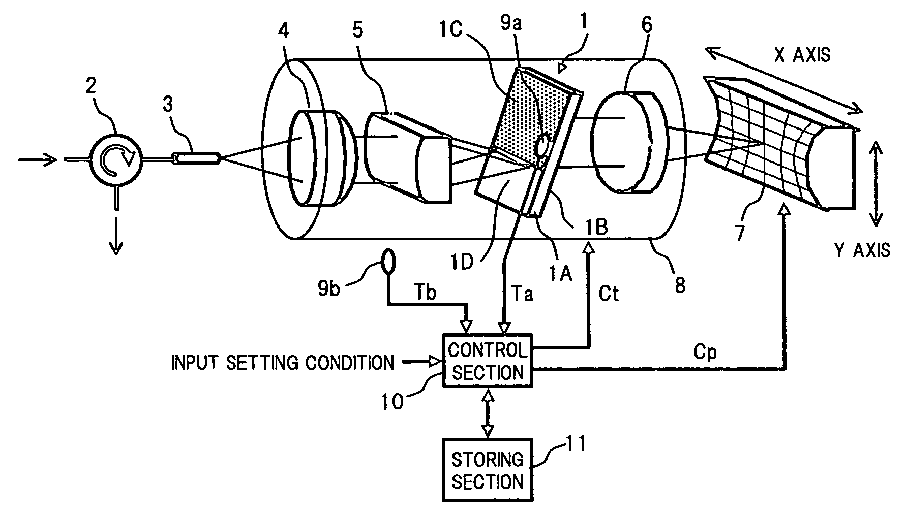
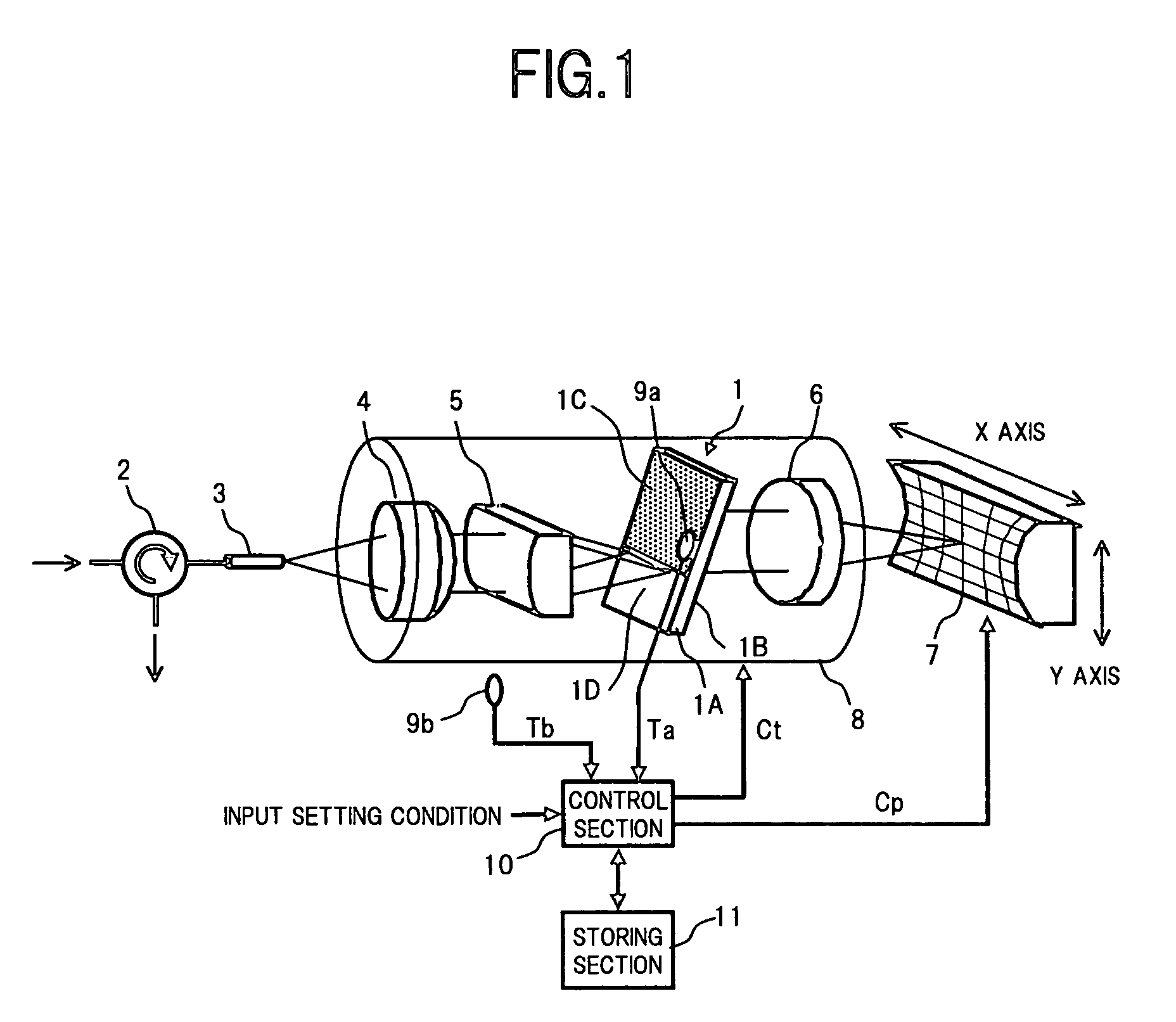
[0028]FIG. 1 is a functional block diagram showing a configuration of one embodiment of a wavelength dispersion compensator according to the present invention.

[0029]In FIG. 1, the wavelength dispersion compensator of the first embodiment comprises, for example: a VIPA plate 1 as a device having two reflective surfaces which are opposed and parallel to each other; an optical system which consists of an optical circulator 2, an optical fiber 3, a collimate lens 4 and a line focal lens 5, enabling a WDM light condensed on a segment to be incident on a radiation window 1D of the VIPA plate 1; a convergent lens 6 condensing an optical beam that has been multiple-reflected by the VIPA plate 1 to be emitted from one of the parallel surfaces, on one point; a free-form surface mirror 7 serving as a reflector, for reflecting the light condensed by the convergent lens 6 at a required position t...


PUM


Abstract

It is an object of the present invention to provide a control technique for reducing wavelength dependence of wavelength dispersion values and also for suppressing a change in wavelength transmission characteristic with a temperature variation or the like, in a VIPA-type wavelength dispersion compensator. In order to achieve the object, the present VIPA-type wavelength dispersion compensator comprises: a VIPA plate capable of emitting incident lights in different directions according to wavelengths; a free-form surface mirror reflecting, at a previously set position, the lights of respective wavelengths emitted from the VIPA plate to return the reflected lights to the VIPA plate; a case provided with a heater which variably changes the temperature of the VIPA plate, a temperature sensor measuring the temperature of the VIPA plate and the ambient temperature; and a control section that reads out data which is measured or the like before starting the operation to be stored in a storing section, according to the measurement result of the temperature sensor, and optimizes the position of the free-form surface mirror and the temperature of the VIPA plate based on the read data.

Description

FIELD OF THE INVENTION[0001]The present invention relates to a control technique for realizing wavelength dispersion compensation with high accuracy for a wavelength dispersion compensator configured utilizing an optical component provided with a function for demultiplexing a wavelength division multiplexed (WDM) light according to wavelengths.DESCRIPTION OF THE RELATED ART[0002]There has been proposed a configuration utilizing so-called a virtually imaged phased array (VIPA) for demultiplexing a WDM light into a plurality of optical beams that can be distinguished spatially according to wavelengths, as one of conventional wavelength dispersion compensators (refer to Japanese Unexamined Patent Publication No. 9-43057 and Japanese National Publication No. 2000-511655).[0003]FIG. 6 is a perspective view showing a configuration example of a conventional VIPA-type wavelength dispersion compensator. Further, FIG. 7 is a top view of the configuration example of FIG. 10.[0004]As shown in e...

Claims


Application Information

Patent Timeline
Patent Type & Authority Patents(United States)
IPC IPC(8): H04J14/02G02B6/32G02B6/34G02B26/00H04B10/07H04B10/2507H04B10/2525
CPCG02B6/29311G02B6/29313G02B6/29314G02B6/29395G02B6/29392G02B6/29394G02B6/29358G02B6/2938
Inventor KAWAHATA, YUICHI
Owner FUJITSU LTD
Why Eureka
Try Eureka