Machine tool with work piece handling arrangement

a technology of workpieces and machine tools, applied in the field of machine tools and workpiece handling arrangements, can solve the problems of large set-up area, large substantial limitation of machine design, so as to reduce the number of pivot axes required for the pick-up arm, reduce the number of times of machine loading and unloading, and facilitate the effect of setting up

Inactive Publication Date: 2008-09-02
GEBR HELLER MASCHFAB GMBH
View PDF13 Cites 7 Cited by
  • Summary
  • Abstract
  • Description
  • Claims
  • Application Information

AI Technical Summary

Benefits of technology

[0011]As the horizontal support beam is disposed on top of the housing, the portal normally extending over the machine tool and the housing is not necessary. The required set up area is reduced and the technical expenditures with regard to the manufacture and construction of the machine tool arrangement or, respectively, the machining setup, are lowered. Furthermore, the chances for faulty mounting and faulty alignments are reduced. The correct position of the horizontal beam is provided by the tool manufacturer. Furthermore, the supply of the work pieces to the machine tool is more precise. The horizontal beam is spatially supported by the housing, whereby the vibrations and oscillation of the horizontal beam are reduced—in comparison with portals whose horizontal beams are supported at their opposite ends by (relatively high) columns.
[0020]The crane may be used for moving individual heavy work pieces and also tools into, and out of, the working area of the machine components. For example, the tools required for internal milling of round openings are generally so heavy that they can not be manually exchanged but require a crane for that purpose. The horizontal beam disposed above the working space can therefore perform a double function, it manually supports the work piece transport device and it also forms the support structure for the crane. It this way, a compact machine arrangement is obtained which is easy to set up, which provides for rapid work piece exchange and which facilitates a comfortable manual tool change-over.

Problems solved by technology

Furthermore, tools need to be replaced occasionally, that is, the old tools have to be moved out of the working space of the machine tool and new tools must be brought into the working space.
This solution however requires a large set-up area.
However, the integration of the loading device into the machine tool represents a substantial limitation with regard to the machine design.

Method used


Image

  • Machine tool with work piece handling arrangement
  • Machine tool with work piece handling arrangement
  • Machine tool with work piece handling arrangement

Examples


Embodiment Construction

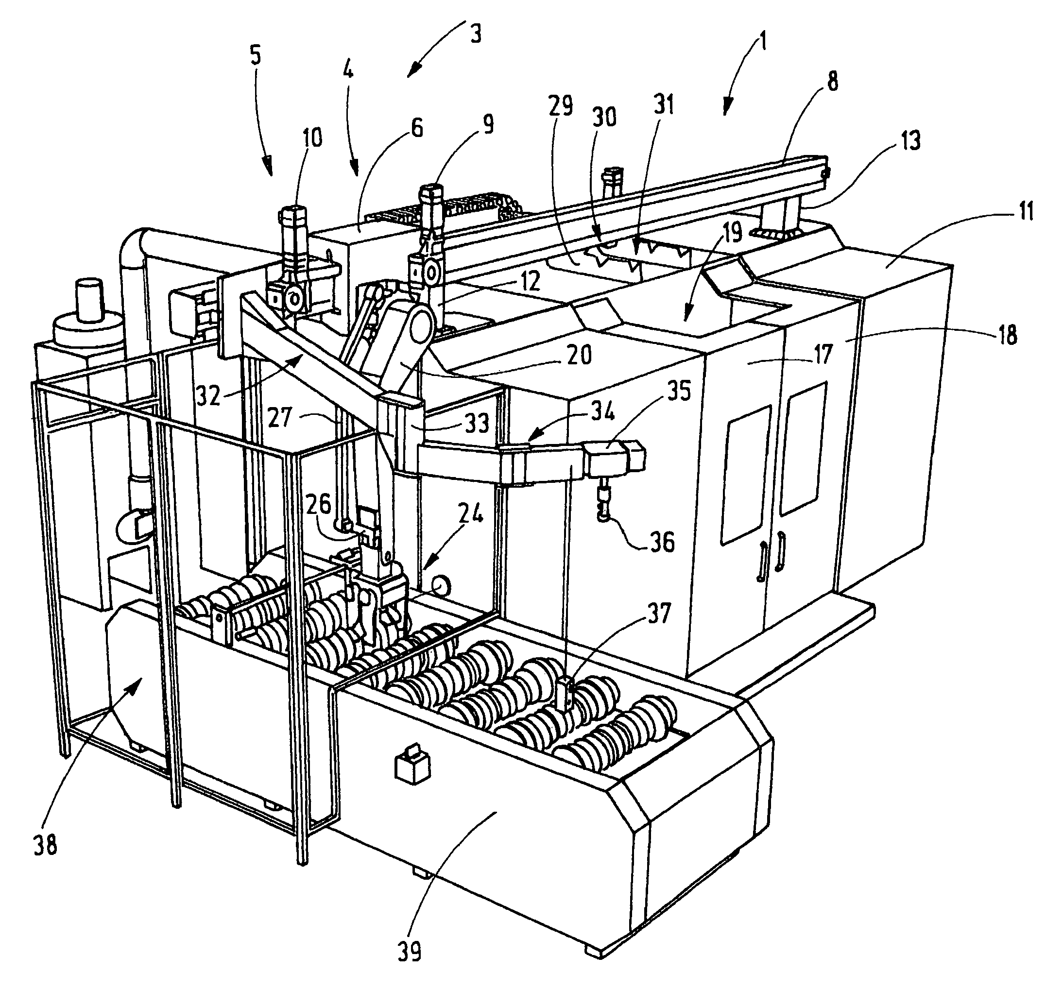
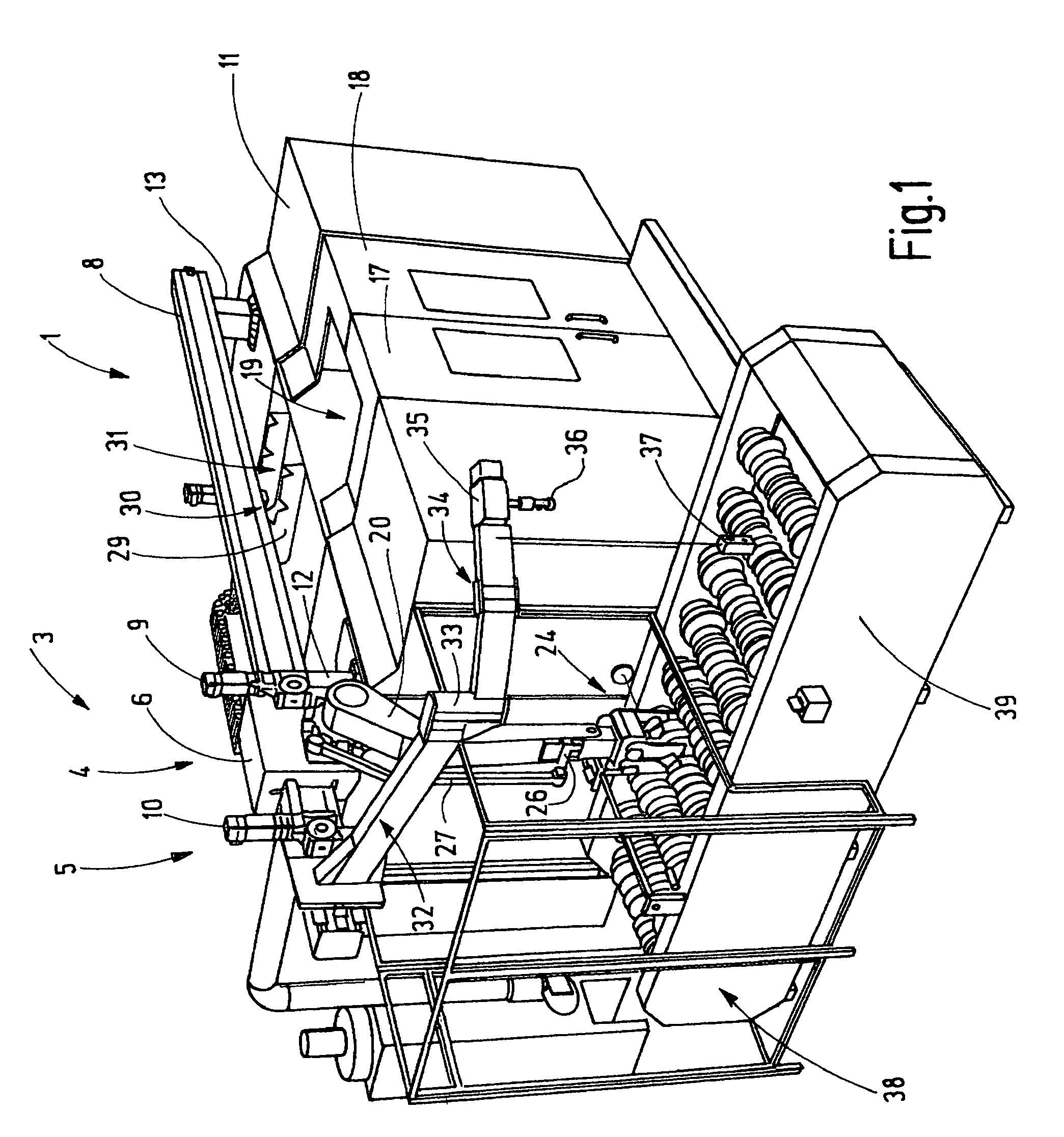
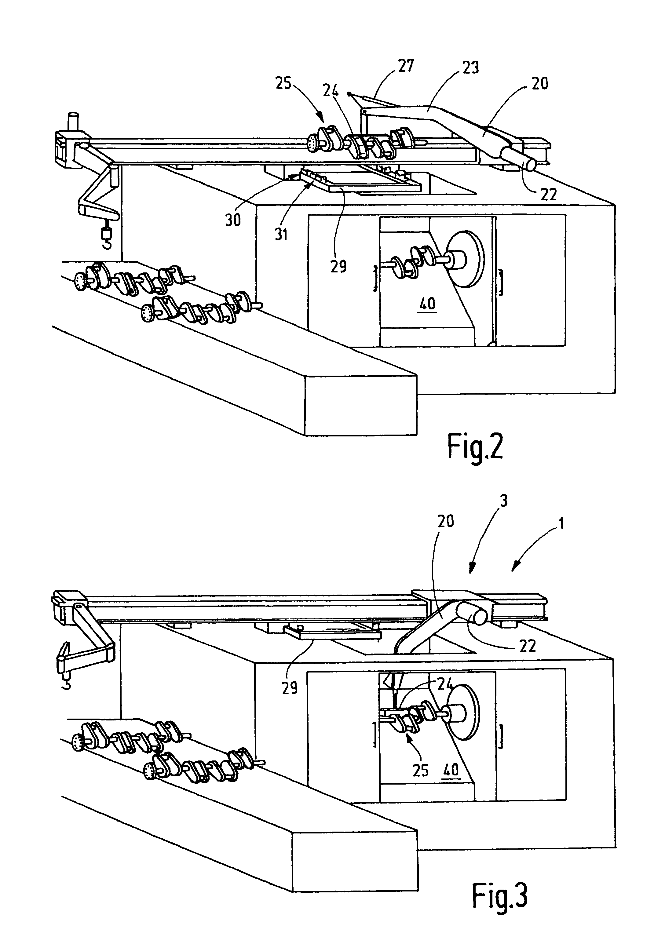
[0026]FIG. 1 shows a machine tool arrangement including a machining structure 1 which comprises a machine component 2 as schematically shown in FIG. 6, for example, in the form of an internal round cylinder cutting machine or another machine for the cutting of work pieces and a transport device 3, for example, a loader 4 for moving work pieces and / or a crane 5 for transporting large tools or work pieces. The loader 4 and the crane 5 include each a carriage 6, 7. The carriages 6, 7 are supported on a common horizontal support beam 8 and movable horizontally between a machine position M and an outer or loading position L (FIG. 5). They are provided with drive units 9, 10, for example servo motors. At least the drive unit 9 of the carriage 6 is position-controlled.

[0027]As shown in FIGS. 1 and 6, the horizontal support beam 8 is disposed on opposite outer walls of the housing 11 of the machine component 2. To this end, it is provided with stands or legs 12, 13 by way of which the horiz...


PUM

PropertyMeasurementUnit
areaaaaaaaaaaa
weightaaaaaaaaaa
transmissionaaaaaaaaaa

Abstract

In a machine tool arrangement comprising a machine tool component including a mounting structure for a work piece to be machined by a suitable metal cutting tool, a housing enclosing the machine tool component, a horizontal support beam is disposed above the housing and carries handling equipment for supplying work pieces from an adjacent loading area to the machine component for machining and returning the finished work pieces to the storage structure and an intermediate storage structure is disposed near the machine tool component for temporarily storing unfinished work pieces to be machined and finished work pieces after being machined.

Description

BACKGROUND OF THE INVENTION[0001]The invention relates to a machine tool and a work piece handling arrangement associated therewith.[0002]Machine tool work pieces which must be supplied to the machine tool and again removed therefrom for which loading devices are used. Furthermore, tools need to be replaced occasionally, that is, the old tools have to be moved out of the working space of the machine tool and new tools must be brought into the working space. For both, there are handling devices, wherein particularly the device for supplying the work pieces to the machine tool make it possible to integrate the machine tool into the flow of parts for an assembly line.[0003]DE 195 00 652 C1 discloses a machine tool which has a work piece handling device which is set up at one side of the machine tool. It is in the form of a portal which is disposed in front of the machine tool and on which a carriage is supported which is movable horizontally toward, and away from, the machine tool. The...

Claims


Application Information

Patent Timeline
Patent Type & Authority Patents(United States)
IPC IPC(8): B23Q3/155B23C1/00B23Q7/14B65G57/00B23C3/08
CPCB23Q7/04B23Q11/0891Y10T409/307616Y10T409/30392Y10T29/5114Y10T29/5176Y10T409/306048Y10T29/17Y10T483/171Y10T483/16
Inventor BONFERT, HEINRICHDEPONTE, GEORGMARKER, WOLFGANGHERKERT, MICHAEL
Owner GEBR HELLER MASCHFAB GMBH
Why Eureka
Try Eureka