Analog-to-digital converter and threshold-value correcting method

a threshold value and converter technology, applied in analogue/digital conversion, physical parameter compensation/prevention, instruments, etc., can solve the problems of affecting the reliability of a-d conversion, affecting the offset of the comparator, etc., and achieve the effect of simple configuration

Active Publication Date: 2008-09-02
SEMICON COMPONENTS IND LLC
View PDF9 Cites 9 Cited by
  • Summary
  • Abstract
  • Description
  • Claims
  • Application Information

AI Technical Summary

Benefits of technology

[0009]By implementing this embodiment, individually turning on and off the input of the input analog voltage to the plurality of comparator circuits is no longer required. Thus, the frequency characteristics for the input analog voltage improve. Thereby, the waveform distortion of the input analog voltage can be reduced. Also, since the input analog voltage inputted to a plurality of comparators is turned on and off in a unified manner, the input of the input analog voltage to a plurality of comparators is controlled easily and more simply.
[0011]The A-D converter may further comprise a constant-voltage source which outputs a plurality of constant voltages having different values to be selected in said threshold voltage selection circuit. The threshold voltage selection circuit may include a group of switches that sequentially switch the selection in the ascending or descending order among the plurality of constant voltages for at least one of said plurality of comparator circuits, when the correction reference analog voltage is inputted to the plurality of comparator circuits. In this case, the selection is sequentially switched in the ascending or descending order, so that the selection of a voltage that serves as threshold values in a plurality of comparators can be made easily.
[0012]The threshold voltage selection circuit may include shift registers which operate the group of switches so that a voltage is selected, as the threshold value, in the ascending or descending order among the plurality of constant voltages having different values. The use of shift registers made it possible to select the voltage for the group of switches in the ascending or descending order by a simple configuration.
[0014]According to this embodiment, the operation of switching the input to a plurality of comparators from the input analog voltage that is to be converted to the correction reference analog signal is done by switching the unified switch, so that the number of switches can be reduced significantly and the frequency characteristics for the input analog voltage can be improved. As a result, the waveform distortion of input analog voltage to be converted can be reduced.

Problems solved by technology

When the quantization width of an A-D converter, namely the range of voltage expressed by 1 bit is small, the offset of the comparator will become an issue.
Hence, the frequency characteristics deteriorate and the frequency deterioration may cause the distortion of waveforms, thus eventually impairing the reliability of A-D conversion.

Method used


Image

  • Analog-to-digital converter and threshold-value correcting method
  • Analog-to-digital converter and threshold-value correcting method
  • Analog-to-digital converter and threshold-value correcting method

Examples


first embodiment

[0024]A first embodiment of the present invention relates to an A-D converter which converts an analog signal into a 3-bit digital signal.

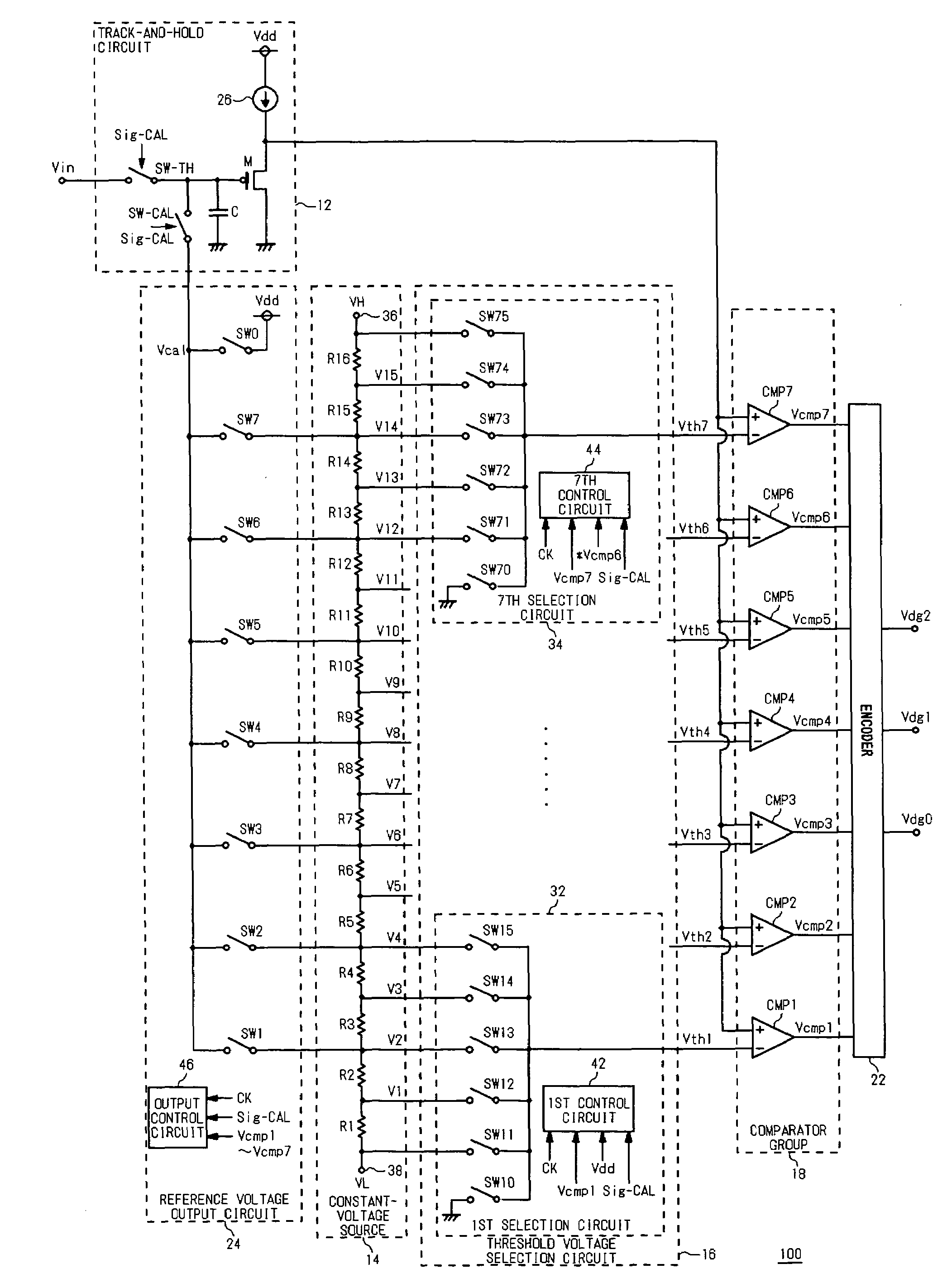
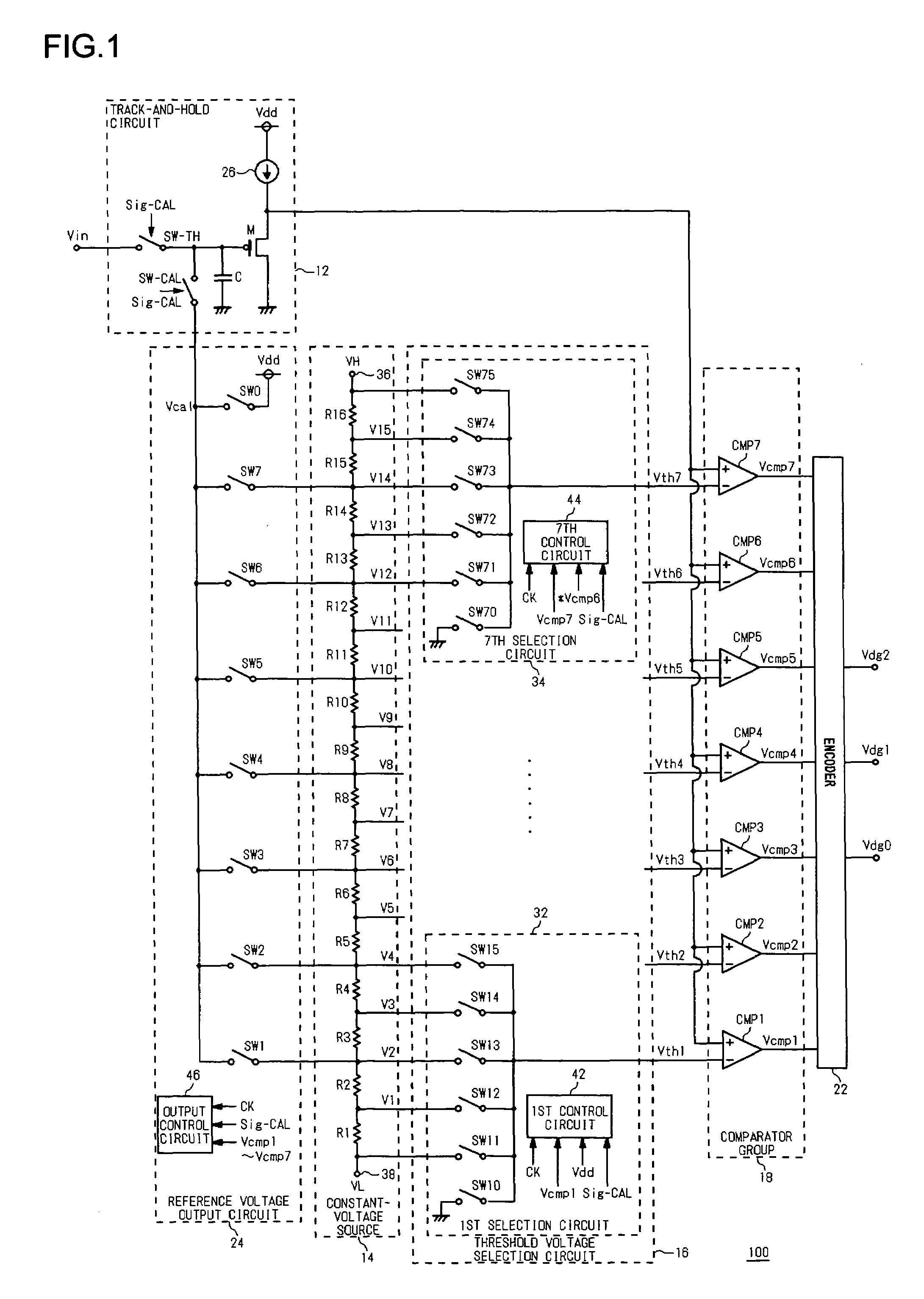
[0025]FIG. 1 illustrates a structure of an A-D converter 100 according to the first embodiment.

[0026]The A-D converter 100 is comprised of a track-and-hold circuit 12, a constant-voltage source 14, a threshold voltage selection circuit 16, a group of comparators 18, an encoder 22 and a reference voltage output circuit 24. The A-D converter 100 has two modes of operation. One is a conversion mode in which A-D conversion is performed and the other is a correction mode in which the offsets of comparators are corrected.

[0027]The group of comparators 18 include a first comparator CMP1 to a seventh comparator CMP7. Noninverting input terminals of the first comparator CMP1 through the seventh comparator CMP7 are connected with the output terminal of the track-and-hold circuit 12. The inverting input terminals of the first comparator CMP1 through the seve...

second embodiment

[0077]In a second embodiment, a description is given of a case where the analog signal is differentially inputted. FIG. 6 illustrates a structure of an A-D converter 300 according to the second embodiment. A positive-phase analog voltage VinA and a reverse-phase analog voltage VinB have 1.0 V as a common potential and are opposite in phase to each other.

[0078]A first track-and-hold circuit 12A and a second track-and-hold circuit 12B may be configured similarly to the track-and-hold circuit 12 shown in FIG. 1, and they operate the same way as the track-and-hold circuit 12 shown in FIG. 1. A first constant-voltage source 14A and a second constant-voltage source 14B may be configured similarly to the constant-voltage source 14 shown in FIG. 1, and the operation thereof is the same as that of the constant-voltage source 14 shown in FIG. 1. A first threshold voltage selection circuit 16A and a second threshold voltage selection circuit 16B may be configured similarly to the threshold vol...


PUM


Abstract

An analog-to-digital converter includes a track-and-hold circuit, a constant-voltage source, a threshold voltage selection circuit, a first comparator to a seventh comparator, an encoder, and a reference voltage output circuit. In a correction mode where the offsets of the first to seventh comparators are to be corrected, a track-and-hold circuit shuts off the input of an analog voltage to the first to seventh comparators by turning off the track-hold switch.

Description

BACKGROUND OF THE INVENTION[0001]1. Field of the Invention[0002]The present invention generally relates to the analog-to-digital conversion technology (hereinafter referred to as “A-D conversion”) and it particularly relates to an analog-to-digital converter (hereinafter referred to as “A-D converter”) having a plurality of comparators connected in parallel wherein the comparator compares the level of reference voltage with the level of analog signal.[0003]2. Description of the Related Art[0004]In an A-D converter, a comparator is used to compare the level of reference voltage with the level of analog signal. When the quantization width of an A-D converter, namely the range of voltage expressed by 1 bit is small, the offset of the comparator will become an issue. Reference (1) listed in the following Related Art List discloses a comparator and an offset correcting converter provided with an offset correcting operation separately from an usual A-D conversion operation.[0005]In Refere...

Claims


Application Information

Patent Timeline
Patent Type & Authority Patents(United States)
IPC IPC(8): H03M1/12
CPCH03M1/1023H03M1/365
Inventor SAKATA, KOHJIOTSUKA, TAKESHI
Owner SEMICON COMPONENTS IND LLC
Why Eureka
Try Eureka