Light emitting device

a technology conversion member, which is applied in the direction of microscope, vehicle headlamp, spectral modifier, etc., can solve the problems of unusability of light emitting device, conversion member discoloration, and light from the light emitting element cannot be fully emitted to the outside, and achieves long service life and high output

Active Publication Date: 2008-09-09
NICHIA CORP
View PDF16 Cites 85 Cited by
  • Summary
  • Abstract
  • Description
  • Claims
  • Application Information

AI Technical Summary

Benefits of technology

[0007]The present invention is intended to solve the above problems, and it is an object thereof to provide a light emitting device with high output and a long service life.

Problems solved by technology

Nevertheless, with the LEDs, LDs, and so forth discussed in WO01 / 040702, when light is emitted from an LED or LD to the outside via a wavelength conversion member, the wavelength conversion member is degraded by heat originating in the light, so that light from the light emitting element can no longer be fully emitted to the outside, or in some cases, the wavelength conversion member becomes discolored and makes the light emitting device unusable, among other such problems.

Method used


Image

  • Light emitting device
  • Light emitting device
  • Light emitting device

Examples


embodiment 1

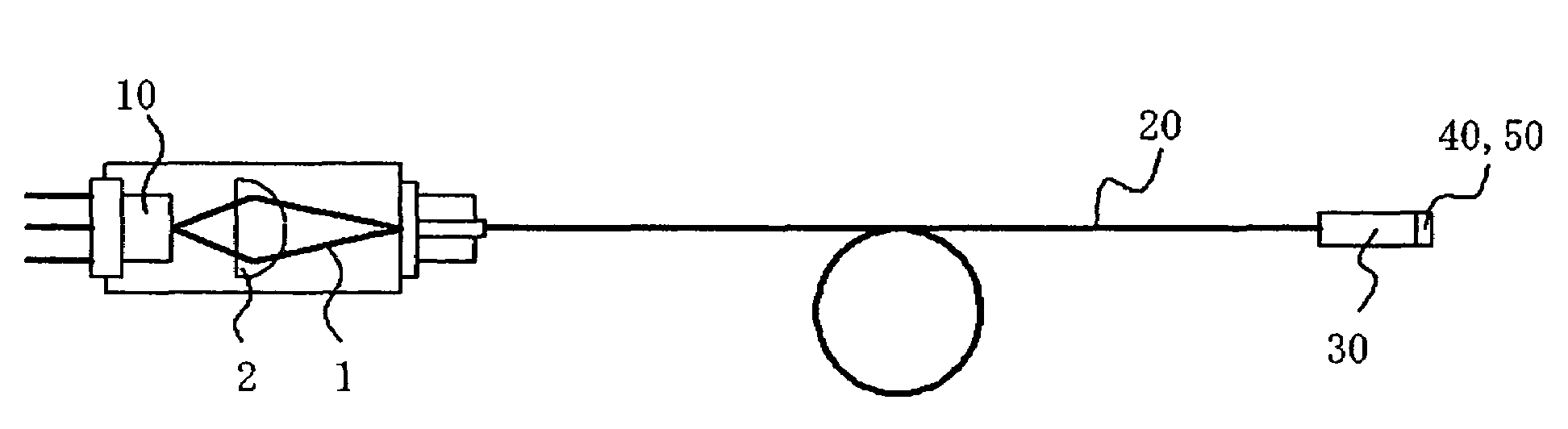
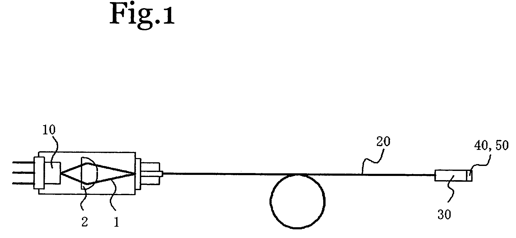
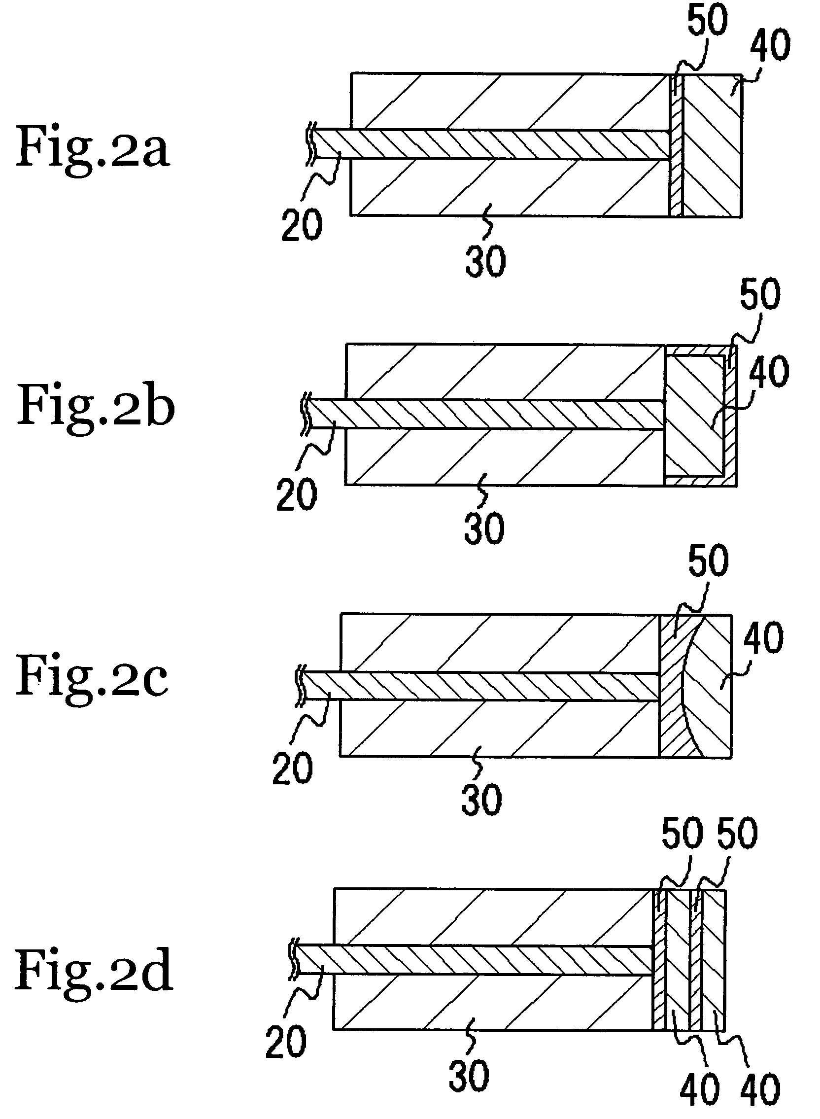
[0054]The light emitting device in this embodiment, as shown in FIGS. 1 and 2a, mainly comprises the light emitting element 10, the light guide member 20, the covering member 30, the wavelength conversion member 40, and the heat conduction member 50. A lens 2 for converging light 1 from the light emitting element 10 is provided on the front face of the light emitting element 10.

[0055]An LD composed of a GaN (gallium nitride)-based semiconductor having an emission peak wavelength near 445 nm is used as the light emitting element 10, a quartz SI-type optical fiber (core diameter of 114 μm, cladding diameter of 125 μm) is used as the light guide member 20, the covering member 30 is composed of alumina and had a diameter of 0.7 mm, the wavelength conversion member 40 comprises two kinds of fluorescent material, namely, 0.53 g of Lu3Al5O12:Ce (emits green light) and 0.2 g of (Sr,Ca)2Si5N8:Eu (emits red light), contained in 1.1 g of silicone resin, and AlN (film thickness of 0.1 mm) is us...

embodiment 2

[0057]The light emitting device in this embodiment, as shown in FIG. 2e, is the same as in Embodiment 1 except that the heat conduction member 50 was formed from ITO. The ITO was formed by sputtering.

[0058]With this light emitting device, degradation of the wavelength conversion member 40 by heat is greatly reduced as compared to a light emitting device not equipped with the heat conduction member 50. As a result, a reliable light emitting device of high emission output can be obtained.

[0059]Furthermore, the present invention can be a light emitting device in which two or more of the unit shown in FIG. 1 are combined. In this case, it is preferable for the wavelength conversion member 40 and the heat conduction member 50 both to be constituted by a single member. Also, the light that is ultimately obtained is not limited to white light, and can instead be green light, for instance.

embodiment 3

[0060]With the light emitting device in this embodiment, as shown in FIG. 5m, an LD composed of a GaN (gallium nitride)-based semiconductor having an emission peak wavelength near 405 nm was used as the light emitting element 10, and a heat conduction member 50 composed of ITO (film thickness of 300 nm) was sandwiched between glass and the wavelength conversion member 40. The ITO was formed by sputtering.

[0061]The wavelength conversion member 40 was formed by mixing as fluorescent substances 2 g of Ca10(PO4)6Cl2:Eu (emits blue light) with 2 g of a liquid mixture of ethyl cellulose and terpineol (weight ratio=12:88), and sintering this mixture for 30 minutes at 80° C., 10 minutes at 200° C., and 1 hour at 500° C. to bake the fluorescent substance. The thickness of the wavelength conversion member 40 was about 500 μm, for example.

[0062]Alternatively, the fluorescent substance was a mixture of 10 g of Ca10(PO4)6Cl2:Eu (emits blue light), 100 g of isopropyl alcohol, 20 g of alumina sol,...


PUM


Abstract

A light emitting device, comprises at least: a light emitting element; a wavelength conversion member for converting the wavelength of light from the light emitting element; a bendable light guide member for guiding light from the light emitting element to the wavelength conversion member; and a heat conduction member that is thermally connected to the wavelength conversion member.

Description

BACKGROUND OF THE INVENTION[0001]1. Field of the Invention[0002]The present invention relates to a light emitting device having a light emitting element, a light guide member, and a wavelength conversion member.[0003]2. Description of the Related Art[0004]There has long been a need for a light emitting device with which color information can be accurately reproduced at high output. The use of light emitting diodes (hereinafter referred to as LEDs), laser diodes (hereinafter referred to as LDs), and other such light emitting elements as the light source for such devices has already been proposed (see, for example, WO01 / 040702).[0005]LEDs and LDs are compact, have good power efficiency, emit light in vivid colors, and eliminate problems such as broken bulbs. In particular, LDs have higher optical density than LEDs, so a light emitting device of higher brightness can be obtained.[0006]Nevertheless, with the LEDs, LDs, and so forth discussed in WO01 / 040702, when light is emitted from an...

Claims


Application Information

Patent Timeline
Patent Type & Authority Patents(United States)
IPC IPC(8): F21V33/00F21K99/00
CPCA61B1/0653A61B19/52G02B6/4202A61B2019/5206A61B2018/2255A61B1/128A61B90/36A61B2090/306F21S41/16F21S41/176F21S41/19H01S5/0087H01S5/02251A61B2018/2288
Inventor HAMA, ATSUTOMOHAYASHI, YUKIHIRO
Owner NICHIA CORP
Why Eureka
Try Eureka