
Resistive torsional mode damping system and method

a damping system and torsional mode technology, applied in the direction of motor control for motor oscillation damping, dynamo-electric converter control, electric generator control, etc., can solve problems such as mechanical damage, affecting the network, and difficult to avoid torsional oscillation in the motor or generator drive train by conventional countermeasure techniques

Inactive Publication Date: 2008-09-09
GENERAL ELECTRIC CO
View PDF39 Cites 56 Cited by
  • Summary
  • Abstract
  • Description
  • Claims
  • Application Information

AI Technical Summary

Benefits of technology

"The present invention is a system and method for damping torsional vibrations on a machine shaft using a resistive torsional mode damping system. The system includes a sensor to measure torque on the shaft, a controller to detect the presence of torsional vibration at the shaft's natural frequency and generate control signals to damp the vibration, and a damper with a damping converter and a resistor to provide the control signals to the shaft. The damper is connected to the machine through a power bus and has a power rating that is less than or equal to about five percent of the machine's normal power rating. The technical effect of this invention is to reduce torsional vibrations on the machine shaft, leading to improved performance and efficiency."

Problems solved by technology

Mechanical damage can occur over time if an electric network exchanges significant energy with a generator at one or more of the natural frequencies of the shaft systems.
In such power systems, the loads are typically large relative to the network (such that the loads can potentially affect the network).
With increasing ratings of electrical motors and drives in these systems, the mechanical and electrical dynamics are increasingly coupled, thus making it difficult to avoid torsional oscillations in motor or generator drive trains by conventional countermeasure techniques.

Method used


Image

  • Resistive torsional mode damping system and method
  • Resistive torsional mode damping system and method
  • Resistive torsional mode damping system and method

Examples


Embodiment Construction

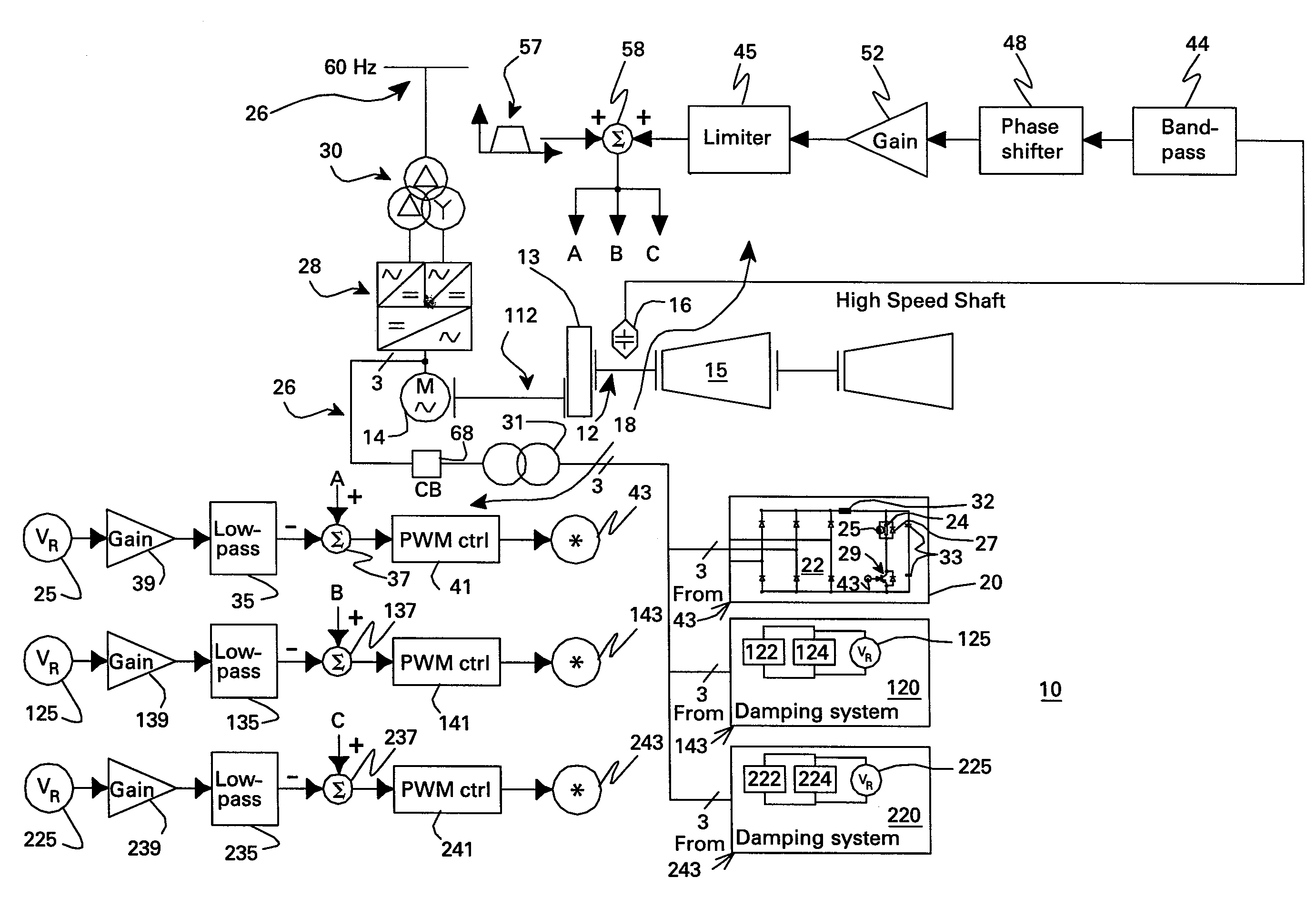
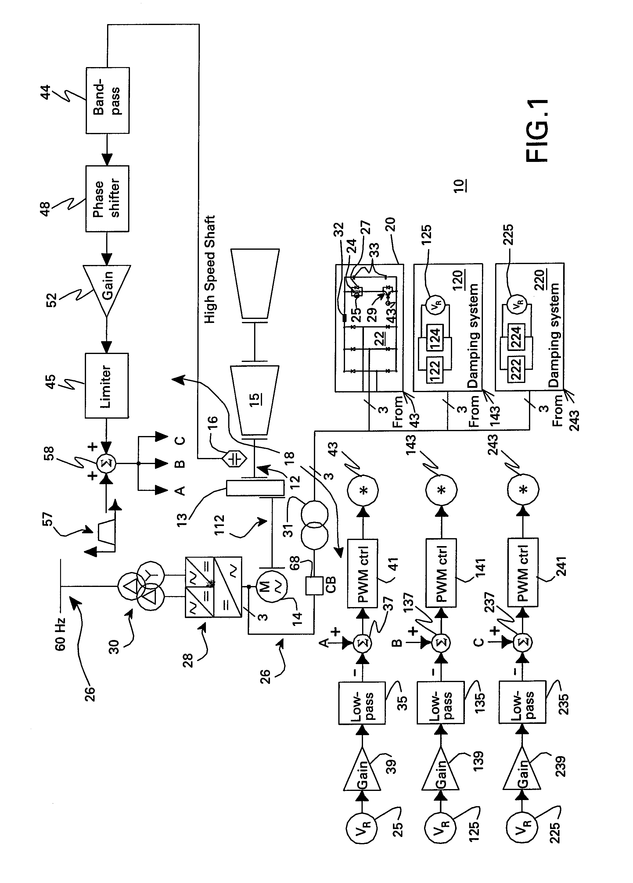
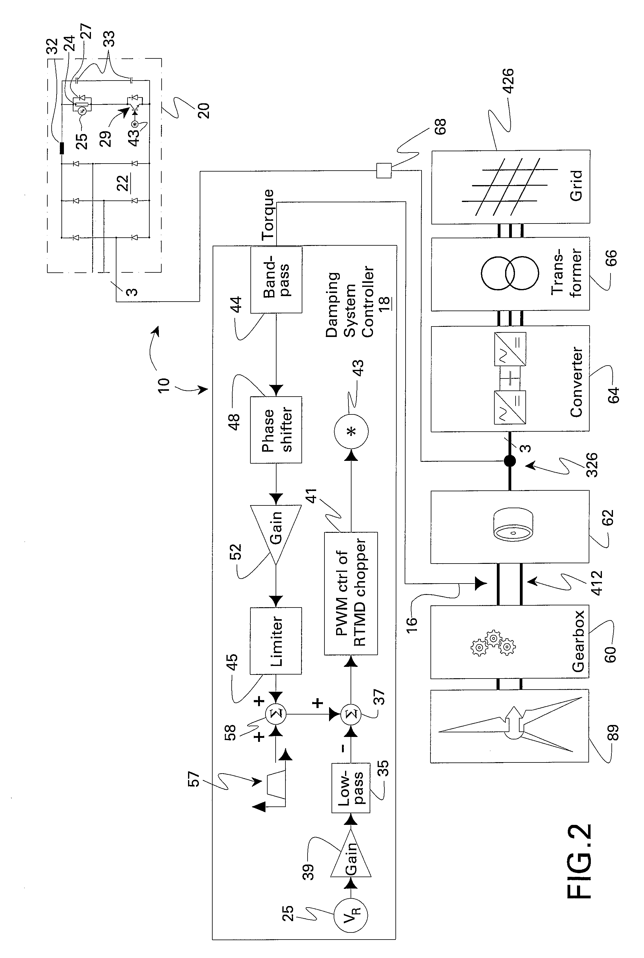
[0018]FIG. 1 is a block diagram of a resistive torsional mode damping system 10 for a shaft 12 of a machine 14. Damping system 10 comprises a sensor 16 configured for sensing a signal representative of torque on shaft 12 and a controller 18 configured for using the sensed signal for detecting a presence of a torsional vibration on shaft 12 corresponding to a natural frequency of the shaft assembly and for generating control signals for damping the torsional vibration (which is shown in two separate portions 1 of FIG. 1 for purposes of fitting FIG. 1 on one sheet). Damping system 10 further comprises a damper 20 comprising a damping converter 22 and resistor 24 coupled to a DC output of damping converter 22. The damping converter is coupled to machine 14 through a power bus 26 (sometimes referred to as a bus bar or grid). The damping converter typically has power rating on the order of less than or equal to about five percent of a nominal power of machine 14. As used herein “converte...


PUM


Abstract

A resistive torsional mode damping system for a shaft of a machine includes: a sensor configured for sensing a signal representative of torque on the shaft; a controller configured for using the sensed signal for detecting a presence of a torsional vibration on the shaft corresponding to a natural frequency of the shaft and for generating control signals for damping the torsional vibration; and a damper including a damping converter and resistor coupled to a DC output of the damping converter, the damping converter being coupled to the machine through a power bus and having a power rating on the order of less than or equal to about five percent of a nominal power of the machine.

Description

BACKGROUND[0001]The invention relates generally to damping torsional vibrations.[0002]Shaft assemblies in strings of prime movers and loads comprising turbine generators, electrical motors, or compressors, for example, sometimes exhibit weakly damped mechanical resonances (torsional modes) with frequencies which can also fall below the network synchronous frequency. Mechanical damage can occur over time if an electric network exchanges significant energy with a generator at one or more of the natural frequencies of the shaft systems. Conventional countermeasures for torsional resonance phenomena include efforts to eliminate the source of resonance excitation by, for example, changing the network, operational, or control parameters.[0003]When a power system has a connection to a large utility network with many gigawatts of generated power, electrical loads on the power system have only a negligible effect. In contrast, island power systems have no connection to a large utility networ...

Claims


Application Information

Patent Timeline
Patent Type & Authority Patents(United States)
IPC IPC(8): H02H7/06H02P11/00H02P9/00
CPCH02P23/04G05D19/02H02J3/24H02P9/10
Inventor SIHLER, CHRISTOF MARTIN
Owner GENERAL ELECTRIC CO
Learn More