
Apparatus comprising circuit breaker with adjunct sensor unit

a sensor unit and circuit breaker technology, applied in the direction of emergency protective circuit arrangement, etc., can solve the problems of stand-alone current sensor, complexity of additional wiring, and the modification of standard circuit breakers to accommodate current sensors, so as to reduce wiring, improve accuracy, and reduce engineering time

Inactive Publication Date: 2008-09-09
AIRPAX
View PDF31 Cites 9 Cited by
  • Summary
  • Abstract
  • Description
  • Claims
  • Application Information

AI Technical Summary

Benefits of technology

This solution reduces wiring complexity, decreases engineering time, enhances accuracy, and matches current sensor and circuit breaker ratings, offering improved flexibility and safety while allowing for customizable functions according to user needs and cost constraints.

Problems solved by technology

Stand-alone current sensors have certain disadvantages, including, for example, the complexity of additional wiring and the modification of standard circuit breakers to accommodate the current sensors.

Method used


Image

  • Apparatus comprising circuit breaker with adjunct sensor unit
  • Apparatus comprising circuit breaker with adjunct sensor unit
  • Apparatus comprising circuit breaker with adjunct sensor unit

Examples


Embodiment Construction

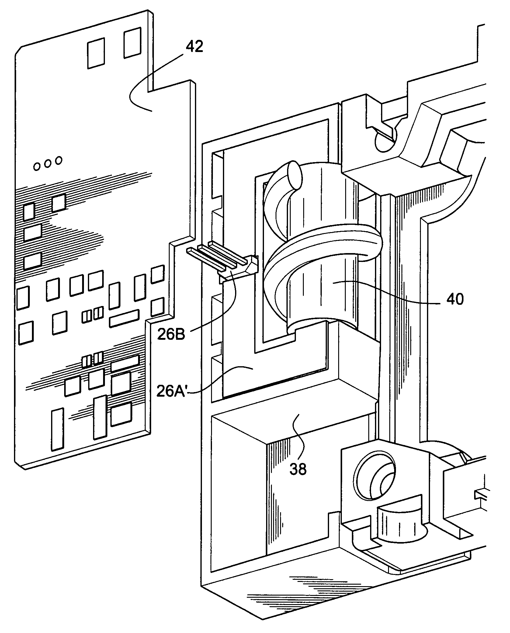
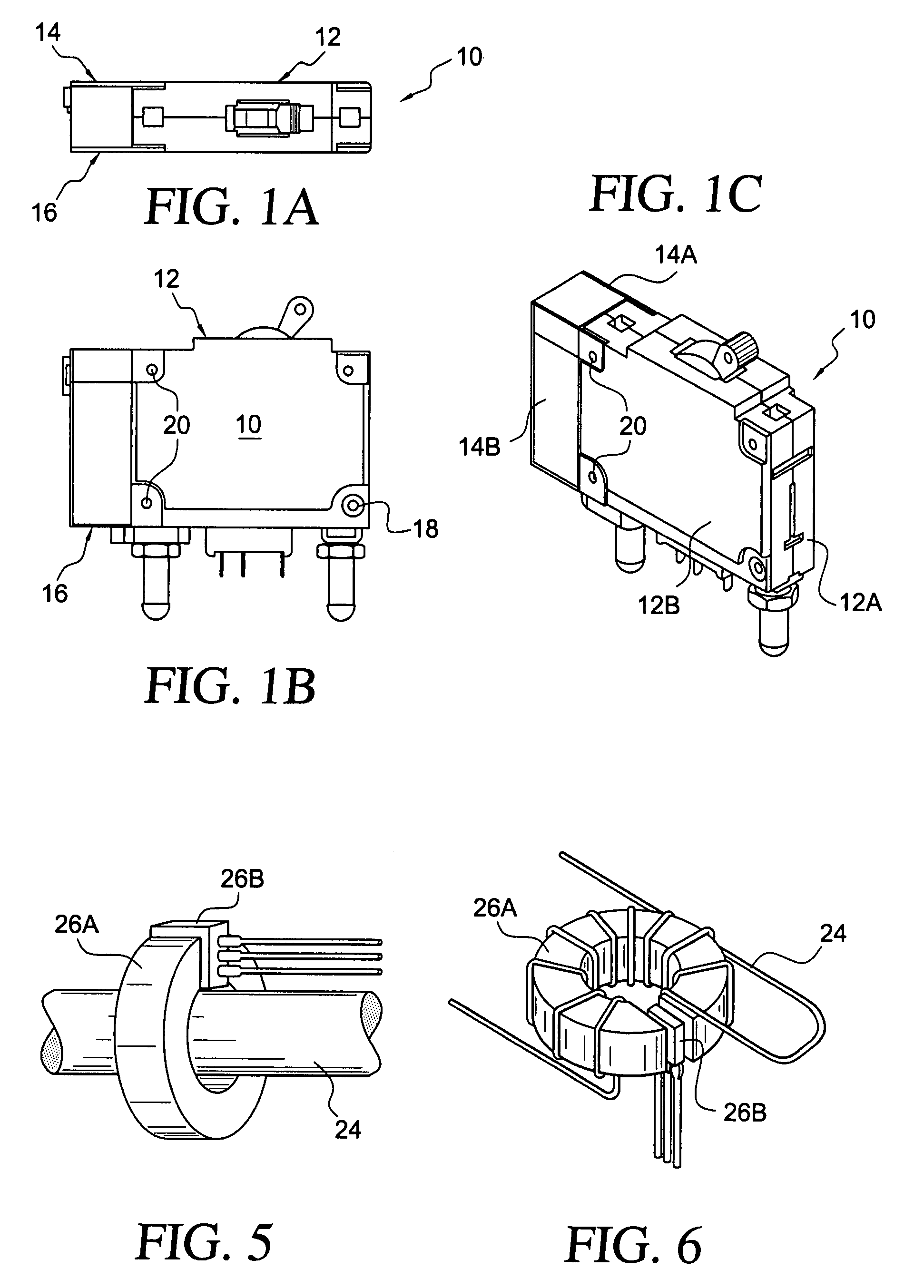
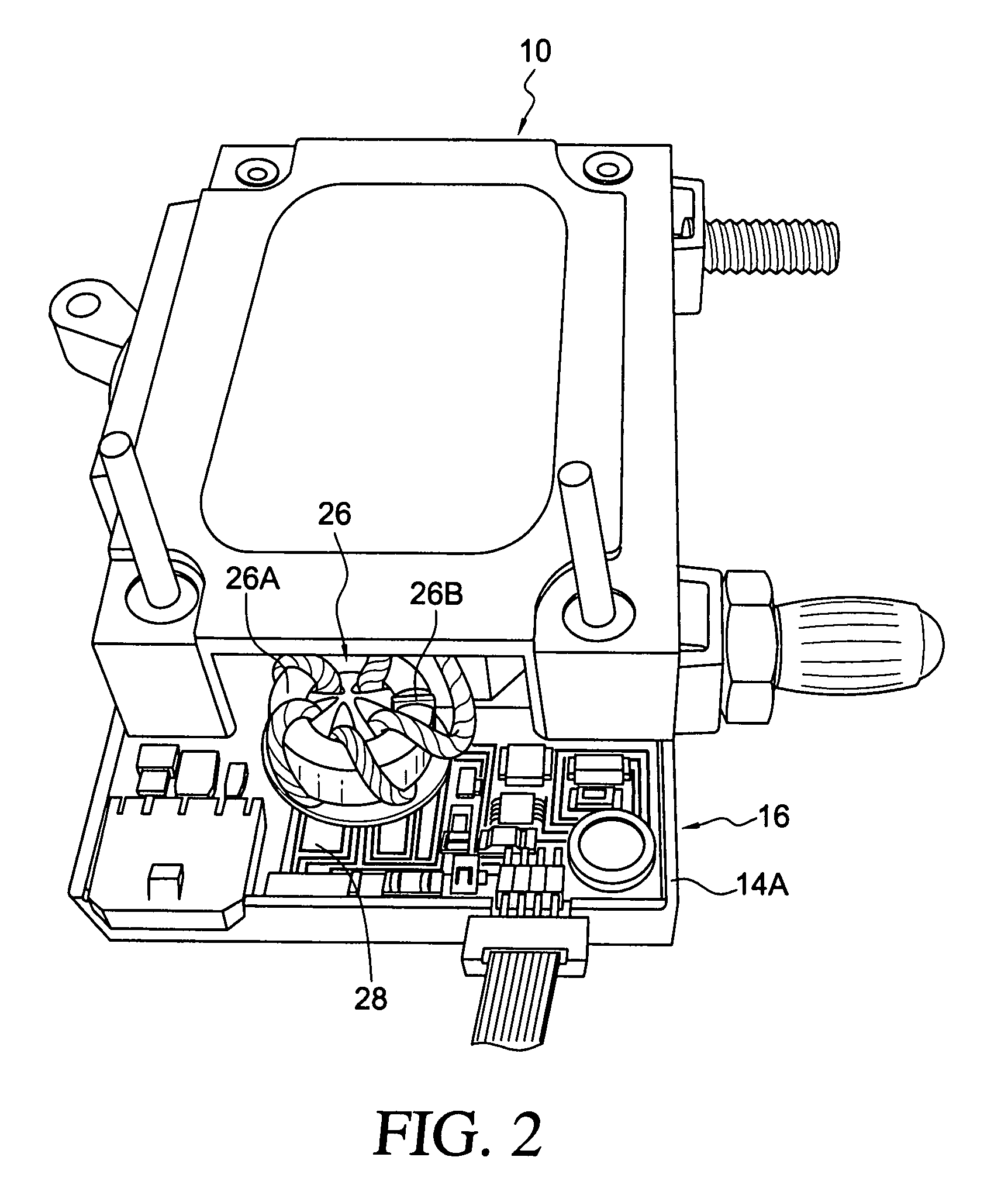
[0017]FIGS. lA, lB, and 1C show a standard IEL (magnetic) circuit breaker 10 having a generally rectangular box-shape case 12 having opposite ends to one which the generally rectangular box-shape case 14 of a current sensor unit 16 is added as an attachment. In the form shown, the case of the circuit breaker is divided along a central plane and is constituted by two generally rectangular box portions 12A, 12B joined at the corners by fasteners such as rivets 18, for example. One of the box portions serves to hold essential parts of the circuit breaker, while the other box portion serves as a cover of the circuit breaker. The case 14 of the current sensor unit 16 may be similarly constructed. The case portions 14A, 14B are provided with legs 20 that overlap respective corners of the circuit breaker case 12 and that are joined to the. circuit breaker case by the same fasteners 18 that join the portions of the circuit breaker case. FIG. 8A shows a box portion 12A (e.g., half) of a circ...


PUM


Abstract

A self-contained current sensor unit is integrated with a standard circuit breaker as an attachment to the circuit breaker that requires minimal modification of the circuit breaker and that becomes an extension of the case of the circuit breaker. The current sensor unit includes a magnetic structure with a programmable Hall Effect device and may include a power supply, a Hall Effect voltage regulator, and an output signal conditioner.

Description

CROSS-REFERENCE TO RELATED APPLICATION[0001]This application claims the benefit of U.S. Provisional Application No. 60 / 654,074 filed Feb. 18, 2005, incorporated herein by reference.BACKGROUND OF THE INVENTION[0002]Power systems often include multiple circuit breakers used to protect and isolate individual branch circuits powered from a common buss. Such branch circuit breakers are used to protect equipment and wiring from the effects of overcurrent resulting from abnormal overload and short circuit conditions. In certain applications it is desirable or necessary to monitor the current of each branch circuit in order to determine the portion of total buss current drawn by each circuit.[0003]Such current monitoring may be used to meter power consumption for billing purposes, preventive maintenance, load shedding or for other purposes. Power system designers often use off-the-shelf stand-alone current sensors in applications where current monitoring is required. These may take the form...

Claims


Application Information

Patent Timeline
Patent Type & Authority Patents(United States)
IPC IPC(8): H02H3/08
CPCH01H71/125
Inventor DOBBS, EUGENE F.JOHNSTON, MERVYN B.WARE, NOEL KEITH
Owner AIRPAX
Learn More