Cooking device

a technology of cooking device and ash material, which is applied in the direction of meat/fish preservation by drying, transportation and packaging, milk treatment, etc., can solve the problems of ash material falling out of the cook and/or exterior environment, inability to easily re-supply the source material of smoke, and high complexity of supply assembly, so as to reduce or eliminate the above-mentioned deficiencies and facilitate operation.

Active Publication Date: 2008-09-23
MASTERBUILT MFG LLC
View PDF37 Cites 41 Cited by
  • Summary
  • Abstract
  • Description
  • Claims
  • Application Information

AI Technical Summary

Benefits of technology

[0008]The present invention is directed at providing a cooking apparatus such as a smoker cooking apparatus with a smoke generating material supply and / or resupply device as in a release feeder device that is directed at alleviating or reducing the above noted deficiencies in the prior art by providing an easy to operate, not unduly complex smoke generating material feeder or loader that, among other things, preferably allows for a resupply in an on-going smoking process without serious disruption of that smoking process and also provides an easy way to initially supply and / or resupply later the smoke generating material while the cooking apparatus has heated up (as in the desired smoker cook temperature level) with a lower chance of operator or environment burning.
[0010]The cook thus has greater flexibility in the smoking process in that, upon an apparent depletion of smoke generation material, a resupply can be carried out either by a pre-loaded and earlier inserted resupply loader (while cool or prior to reaching the desired smoker temperature) or one that is removed during the smoking process and loaded with the desired amount of resupply smoke generating material reinserted and then dumped. The timing of resupply can be based on factors such as experience, direct observation (e.g., a transparent viewing window in the housing or a preexisting gas access port), sensed parameters (smoke density detector) or on a pre-established schedule (e.g. a time and release with an automated loader with timer). Enhanced flexibility is also found in the ability to resupply with an alternate “flavor” smoke material as in starting with hickory and switching to an alternate or supplemental smoking flavor closer to completion time of an ongoing food item or relative to a switched out cooked food item (e.g., through an access door) and having either a similar smoke generating material or a different “flavor” smoke generating material in the loader ready for supplying the firebox tray without having to remove the higher temperature resupply loader at any point during the smoking process, or if the loader is removed and reloaded with smoke generating material it is done so with minimal disruption to the smoking process. While a fixed in position food support during the smoking process (e.g., slide in food support racks) is preferred under the present invention in line with the desire for avoiding complexity, the present invention also features alternate food support means such as a mechanized moving food support that is internalized (e.g., an internal housing set of food securement means such as skewers which rotate during the smoking process either individually or in an interconnected (e.g., chain link)) fashion or an internal to external mechanized moving food support means as in a timed conveyor system passing in and out of the smoker housing with appropriate smoke sealing ports.
[0011]An additional feature of an embodiment of the present invention is a loader provided with a solid bottom and a receiving area or firebox receiver tray provided with a perforated base to facilitate heat contact and ash release. The removal of the loader is thus made a much cleaner and safer process in that there is avoided ash dissipation during the removal of the loader from the confines of the housing, which in prior art systems can require the removal of still smoldering ash with associated hazards.
[0014]In a preferred embodiment, the smoker includes a double wall arrangement, and preferably is in the form of an insulated housing having a generally mini-bar refrigerator configuration and a door provided over, for example, a majority or more of one side wall such as a hinged door with a sealing strip to seal off the doorway. The sealing strip is formed of a material suitable for handling in excess of the temperature range-involved with standard smoker techniques (e.g., 150° F. to 350° F.). The smoke generated from the smoke generating material can thus be sealed in and maintained in contact with the food product being smoked at a higher efficiency which is beneficial for the preferred smoke processing times of six (6) to twelve (12) hours.
[0021]An embodiment at the invention features a border region of the housing extending about the loader aperture that provides a light friction seal arrangement between the end region of the loader and the side wall of the smoker housing. The border region also preferably includes positioning indicia or some form of markings to designate the setting position, although a non-indicia embodiment is also featured under the present invention. An alternate embodiment features proper tray position alignment means as in a key-hole-slot arrangement in the loader and border region to help an operator determine proper initial orientation which clears following sufficient axial insertion of the loader into the smoker housing (e.g. an L-shaped loader slot which allows axial insertion relative to a housing supported key projection extending into the slot area which L-shaped slot provides for rotation once sufficiently inserted. The opposite end loader cap preferably has a similar substantial sealing arrangement that provides for retraction of the loader (preferably a supported, but not completely withdrawn retraction setting) which provides retracted loader support for facilitating a reloading of smoker material while the smoker is heated up.
[0022]The providing of a sealing strip around the door also helps to maintain a previously achieved smoke / temperature setting. This sealed in relationship also facilitates the low temperature, long time period the food is heated (e.g., it is not uncommon for smoking periods to exceed 8 hours in one setting). With such prolonged times it is also helpful to have the loader tray available to restock the smoke generating material due to complete usage during a first period of the overall smoking period. This can be done in a retraction setting while the smoker is fully heated or can involve an initial dump and then a refill and insertion of the loader while the smoker is cool or before full heat up into a stand-by state until a desired point in time arises wherein the pre-loaded loader is dumped.

Problems solved by technology

Problems associated with the prior art includes difficulty in accessing the tray or smoke generating material support once cooking is initiated and the heat level rises to near or at the cooking temperature, the inability to easily re-supply the smoke generating source material without seriously disrupting an ongoing smoking process (e.g., an excessive release of built up smoke and / or heat), and / or a removal from the firebox housing of at least some of the currently utilized smoke generating material (which can also lead to ash material falling out on the cook and / or exterior environment), and / or the reliance on a highly complex supply assembly as exemplified by U.S. Pat. No. 5,138,939.
In addition, due to the lower heat, longer time often associated with smoking food, when the fuel source is of the replenishment type (e.g., charcoal or wood fuel), the fuel itself often needs to be replenished during the course of a single food smoking operation.
This need to resupply also leads to heat release from the firebox housing and the potential for release of smoke, ashes, etc.

Method used


Image

  • Cooking device
  • Cooking device
  • Cooking device

Examples


Embodiment Construction

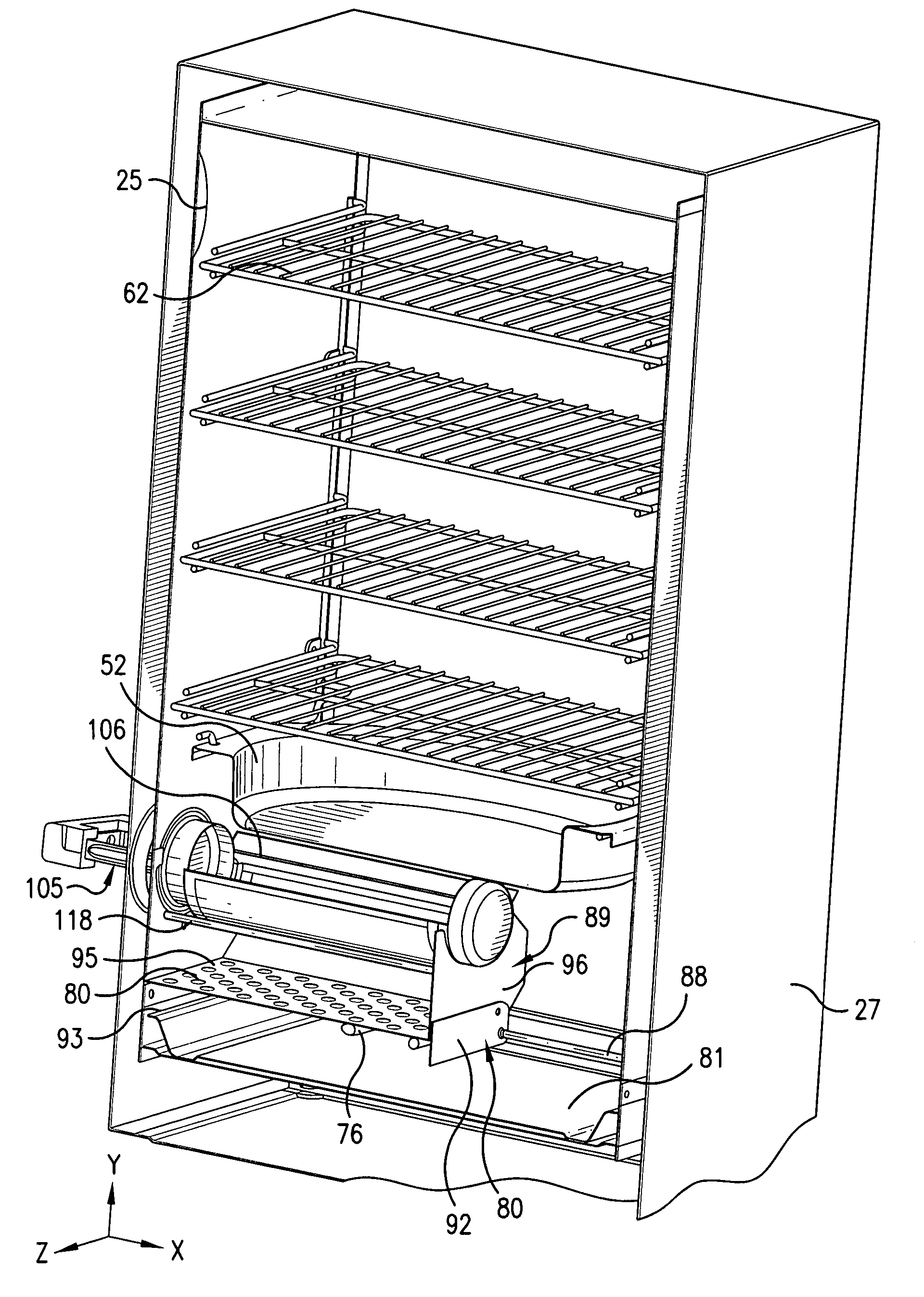
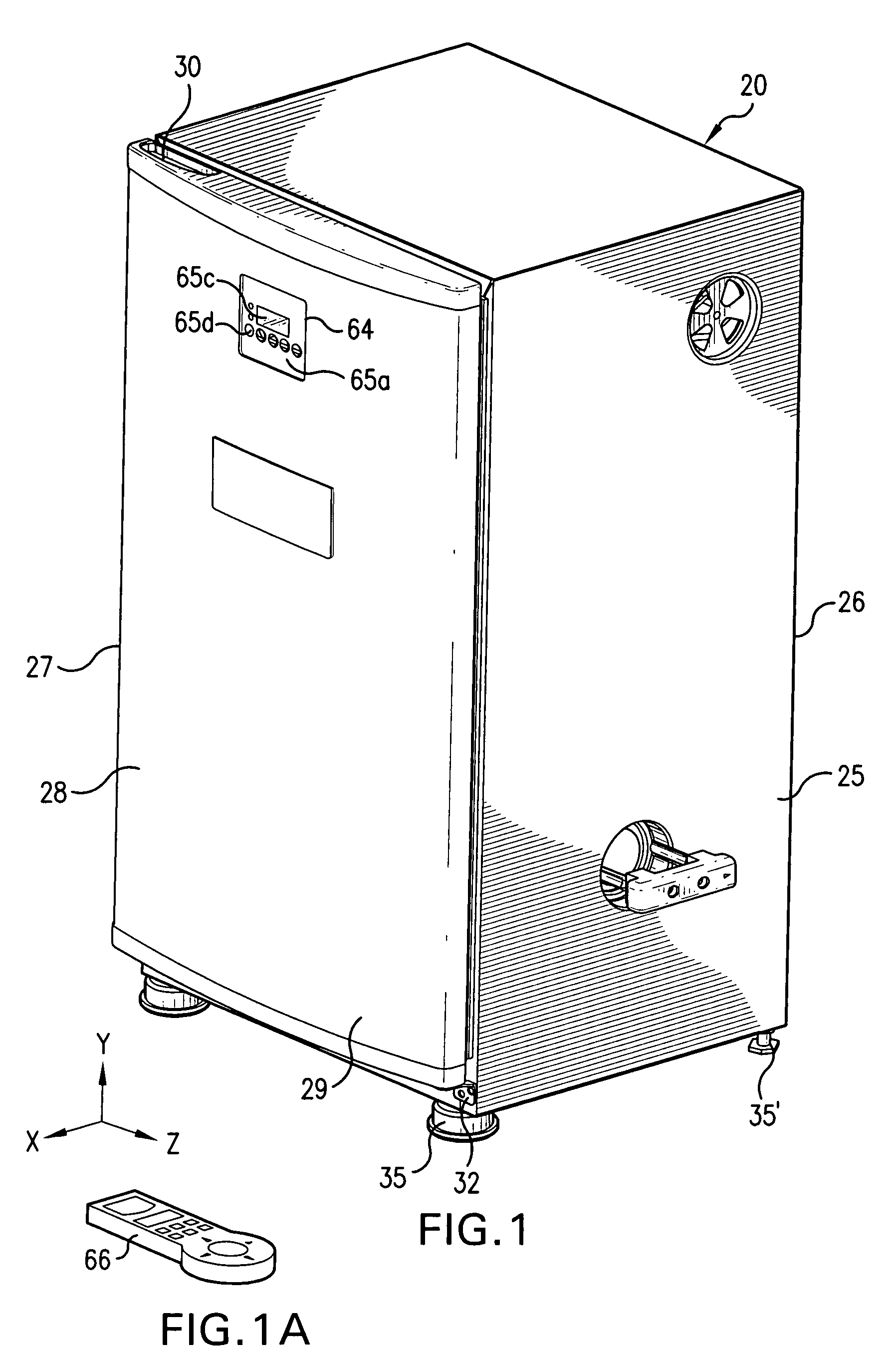
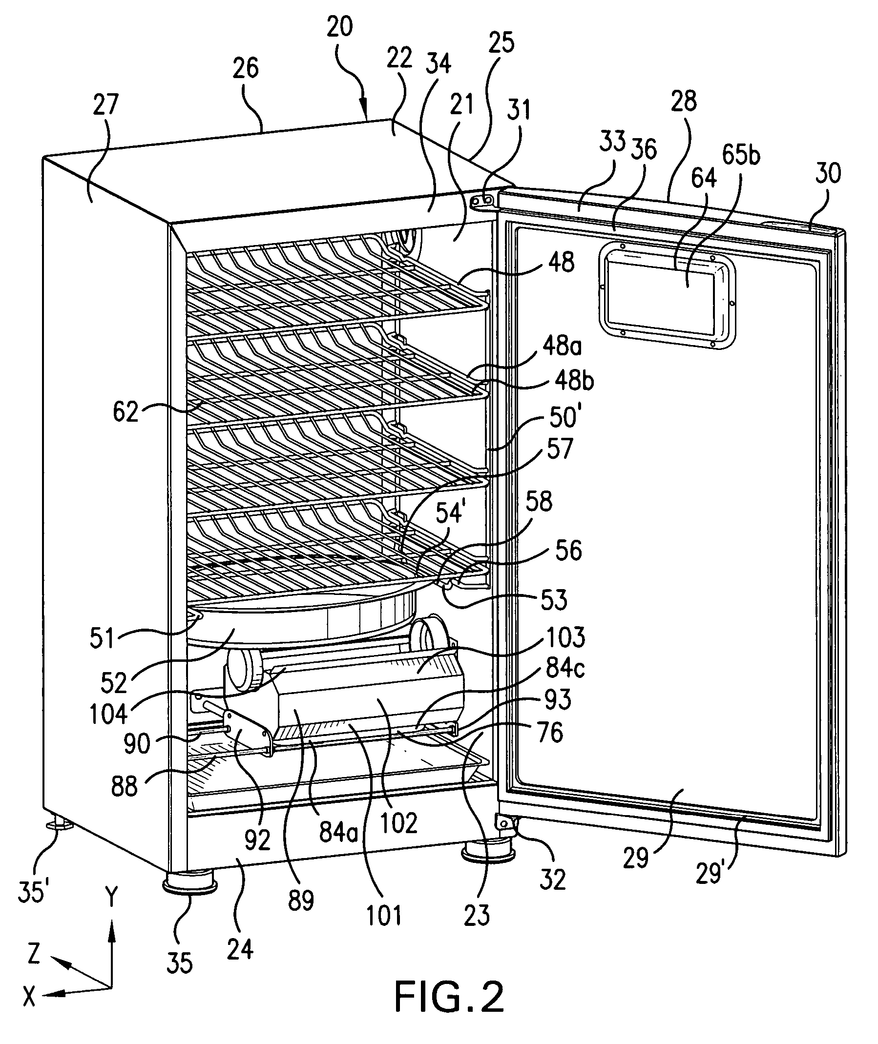
[0044]FIGS. 1 and 2 illustrate smoker cooking apparatus 20 (“smoker”) with FIG. 2 showing door 29 swung open for viewing the interior 21 of housing 22 comprised of main housing section 23 and base housing section 24. In the illustrated embodiment, smoker cooking apparatus 20 has a rectangular side wall configuration comprised of side walls 25, 26, 27 and 28. Side wall 28 is partly (or entirely) comprised of door 29 shown in FIG. 2 as having grasping handle 30 (upper edge positioning) and is supported by an upper and lower hinge assembly 31, 32 with the lower edge of the door being shown below the border between the base housing section 24 and the main housing section 23 in refrigerator door fashion.

[0045]As shown in FIG. 2, the periphery 33 of door 29 and / or corresponding edging 34 of housing 22 are designed for an airtight fit which is facilitated by seal 36 which preferably is secured within a recessed edge 29′ of the door's periphery cavity. Seal 36 is arranged to partially exten...


PUM


Abstract

A smoker having a smoke generating material loader which preferably is insertable and retractable through a housing aperture and is adjustable between a no dump state and a dump state once inserted, preferably relative to a receiver tray that is closer to a heat source, as in an electric heat resistance bar, to cause smoke generation of smoke generating material received from the loader when placed in a dump state. The loader preferably has one or more seal off end caps or sections relative to the receiving housing aperture to provide a heat retention function. A preferred embodiment features a nested arrangement between the inserted loader and receiver tray and preferably the receiver tray is in a sliding supported relationship with the loader as in a semi-cylindrical loader main body in contact with one or more concave supporting surfaces of the receiver tray. The receiver tray also preferably has opposing shielding walls extending up from opposite sides of an apertured base receiving tray. The opposing shields also preferably having an upper constricted opening in close proximity to a rotating loader main body and at a common height with the constricting opening brought about by the nesting arrangement.

Description

FIELD OF THE INVENTION[0001]The present invention comprises a cooking device with a release feeder device as in a smoker apparatus with a smoke generating material loader that is preferably manipulated (e.g., dialed) between a storage mode and a release mode, wherein a supply of wood chips or some other smoke generating material is released to a receiving area of the cooking apparatus as in a receiver tray and subjected to a heat source.BACKGROUND OF THE INVENTION[0002]Both indoor and outdoor grilling has continued to increase in popularity and, in the United States alone, it is estimated that 75% of US households have an outdoor cooking grill, which percentage further increases when indoor grilling is also taken into consideration. This increased popularity with grilling has led to more sophisticated cookers who are no longer satisfied with merely cooking over a bed of charcoal, but have moved into alternate food preparation techniques as in smoking food to prepare a delicious, suc...

Claims


Application Information

Patent Timeline
Patent Type & Authority Patents(United States)
IPC IPC(8): A23L1/01A23L5/10
CPCA23B4/052
Inventor MCLEMORE, DONMCLEMORE, JOHN D.
Owner MASTERBUILT MFG LLC
Why Eureka
Try Eureka