Advanced thermal sensor

a technology of thermal sensors and integrated circuits, applied in the field of advanced thermal sensors, can solve the problems of increasing the complexity of integrated circuits such as microprocessors, increasing the amount of heat generated within the circuit, and increasing the power that is typically consumed by these integrated circuits. to achieve the effect of reducing the complexity and size of thermal sensors

Active Publication Date: 2008-09-23
KIOXIA CORP
View PDF33 Cites 24 Cited by
  • Summary
  • Abstract
  • Description
  • Claims
  • Application Information

AI Technical Summary

Benefits of technology

[0010]One or more of the problems outlined above may be solved by the various embodiments of the invention. Broadly speaking, the invention includes systems and methods for reducing the complexity and size of thermal sensors, where the voltage of a thermally sensitive device is compared to a reference voltage that varies as a function of temperature, rather than being constant.

Problems solved by technology

Integrated circuits such as microprocessors are becoming increasingly complex.
As the number of circuit components and functions grows, the amount of power that is typically consumed by these integrated circuits typically also increases.
With the increased power consumption of the circuits, the amount of heat generated within the circuits increases as well.
This heat may affect the performance of the devices, and may even cause the devices to fail.
As a result of the dangers presented by the generation of increased amounts of heat in electronic devices, it is often necessary to be able to detect temperatures within these devices.
As a result, the source of the reference voltage is typically a complex circuit that includes a relatively large number of components and occupies a relatively large area on the chip in which it is implemented.

Method used


Image

  • Advanced thermal sensor
  • Advanced thermal sensor
  • Advanced thermal sensor

Examples


Embodiment Construction

[0032]One or more embodiments of the invention are described below. It should be noted that these and any other embodiments described below are exemplary and are intended to be illustrative of the invention rather than limiting.

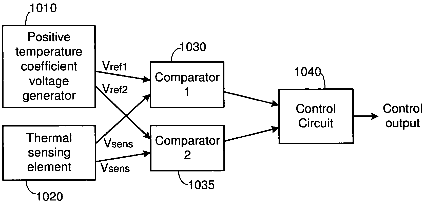
[0033]Broadly speaking, the invention includes systems and methods for reducing the complexity and size of thermal sensors, where the voltage of a thermally sensitive device is compared to a reference voltage that varies as a function of temperature, rather than being constant. In one embodiment, a diode is used to generate a first voltage that decreases as a function of temperature. One or more reference voltages that increase as functions of temperature are also generated. The first voltage is then compared to the reference voltages. When the first voltage is equal to one of the reference voltages, the temperature of the diode and the reference voltage generation circuit(s) is equal to a known temperature. This known temperature is different for each of the...


PUM

PropertyMeasurementUnit
temperatureaaaaaaaaaa
voltageaaaaaaaaaa
sensor voltageaaaaaaaaaa

Abstract

Systems and methods for reducing the complexity and size of thermal sensors, where the voltage of a thermally sensitive device is compared to a reference voltage that varies as a function of temperature, rather than being constant. One embodiment comprises a thermal sensing system including a reference voltage generator, a thermal sensor and a comparator. The reference voltage generator is configured to generate a non-constant reference voltage that varies as a known function of temperature. The thermal sensor is configured to generate a sensor voltage that also varies as a known function of temperature. The functions of the reference and sensor voltages cross at a known temperature / voltage. The comparator is configured to compare the sensor voltage and the reference voltage and to generate a comparison output signal based on the comparison of the sensor voltage and the first reference voltage. A transition in this signal indicates the reference temperature.

Description

RELATED APPLICATIONS[0001]This application is related to U.S. patent application Ser. No. 10 / 441,726, entitled “Thermal sensing circuits using bandgap voltage reference generators without trimming circuitray,” filed on May 20, 2003 by Yoshida.BACKGROUND[0002]1. Field of the Invention[0003]The present invention relates generally to electronic devices, and more particularly to systems and methods for sensing the temperature of devices such as integrated circuits.[0004]2. Related Art[0005]Integrated circuits such as microprocessors are becoming increasingly complex. The circuit components (e.g., transistors, diodes, resistors and the like) that form these devices are, at the same time, becoming increasingly small so that more and more functions may be performed by a particular integrated circuit. As the number of circuit components and functions grows, the amount of power that is typically consumed by these integrated circuits typically also increases. With the increased power consumpt...

Claims


Application Information

Patent Timeline
Patent Type & Authority Patents(United States)
IPC IPC(8): G01K7/01G01K7/14
CPCG01K7/01G01K3/005
Inventor YOSHIDA, MUNEHIRO
Owner KIOXIA CORP
Why Eureka
Try Eureka