Lidar

a lidar and mirror technology, applied in the field of lidar, can solve the problems of affecting the accuracy of lidar, so as to reduce scattering, save the loss caused by semi-translucent mirrors, and improve efficiency

Active Publication Date: 2008-09-23
VAISALA
View PDF7 Cites 12 Cited by
  • Summary
  • Abstract
  • Description
  • Claims
  • Application Information

AI Technical Summary

Benefits of technology

[0022]Object of the invention is to create an improved optical structure for lidar, in which it would be possible to combine more than previously of the beneficial aspects of the aforementioned prior art, while simultaneously avoiding at least some of the problems associated with the prior art. An object of the invention is particularly to create an optical structure, which, in terms of its structural properties would permit
[0032]In the solution according to the invention, the alignment of the light can thus take place with the aid of a single optical system while nevertheless be arranged so that the field of vision of the receiver and the transmitter beam do not coincide in the near zone of the lidar. This permits greater stability than with the known biaxial structure, and simultaneously less near-zone scattering than in the known coaxial lidar.
[0034]In one embodiment of the invention, the transmitter beam and the field of vision of the receiver are located in the optical system at a distance to each other, in such a way that a so-called ‘dark’ zone remains in the near zone of the lidar, between the transmitter beam and the field of vision of the receiver. The ‘dark’ zone is thus located annularly around the transmitter beam while the field of vision of the receiver is located around the ‘dark’ zone. In the embodiment in which the transmitter beam surrounds the field of vision, the ‘dark’ zone is located correspondingly around the receiver beam. The ‘dark’ zone is thus a zone, which the transmitter beam does not strike and which also is not included in the field of vision of the receiver. The implementation of the ‘dark’ zone between the field of vision and the transmitter beam further significantly reduces the scattering from the transmitter beam to the receiver, in the near zone of the lidar. As the distance increases, the transmitter beam and the field of vision diverge, i.e. expand, so that despite the ‘dark’ zone, the field of vision and the transmitter beam begin to partly overlap each other within the measurement zone of the lidar.
[0036]In a third embodiment of the invention, the shapes of the transmitter beam and the field of vision are essentially rotationally symmetrical around their common central axis. This achieves the additional advantage that the symmetry of the system at least partly compensates for the object's possibly asymmetrical reflecting or scattering behaviour.

Problems solved by technology

In the coaxial solution according to FIG. 1, a problem arises in the form of crosstalk and excessive scattering in the near zone of the lidar, or at close measurement distances.
Excessive near-zone scattering can upset measurement in the lidar's entire measurement range, because the receiver 2 can then become saturated by the excessively strong backward signal.
However, the solution is more complex and expensive, as it requires separate optical systems, typically lenses and systems of lenses, for both the receiver and the transmitter.
Because the optical systems of the receiver and transmitter are separate from each other, the internal focussing of the apparatus is also difficult.
The focussing error can also change during operation, due to mutual movement between the optical systems or vibration, so that measurement becomes unstable.
In addition, in principle an error can arise from the fact that the scattering or reflection of the object and the medium do not behave symmetrically in relation to the transmitter beam.
All in all, biaxial lidar is less stable than coaxial lidar of corresponding quality.
In addition, the small alignment error of the transmitter beam and the field of vision of the receiver is compensated at least partially by the fact that the field of vision of the receiver is located around the transmitter beam.
A drawback with the Cassegrain solution is its complexity.
This means that making the solution according to FIG. 2 ready to operate is quite demanding.
The parallel alignment of the beams can be particularly difficult, if it must be carried out in field conditions after the lidar has been moved.
Thus, each of the known solutions referred to above has its own drawbacks, which reduce its attractiveness and usefulness.
A coaxial solution like that shown in FIG. 1 has the problem of excessive near-zone scattering.
A biaxial solution has, in turn, the problem of aligning the transmitter beam and the receiver beam and the very great influence of an alignment error on the strength of the received signal.
In the solution according to FIG. 2, though an alignment error between the transmitter beam and the receiver beam has less effect than in the biaxial solution, the actual alignment is even more difficult that in the biaxial solution.
In other ways too, the device shown in FIG. 2 is complex and demands more alignment operations that the other solutions.

Method used


Image

  • Lidar
  • Lidar
  • Lidar

Examples


Embodiment Construction

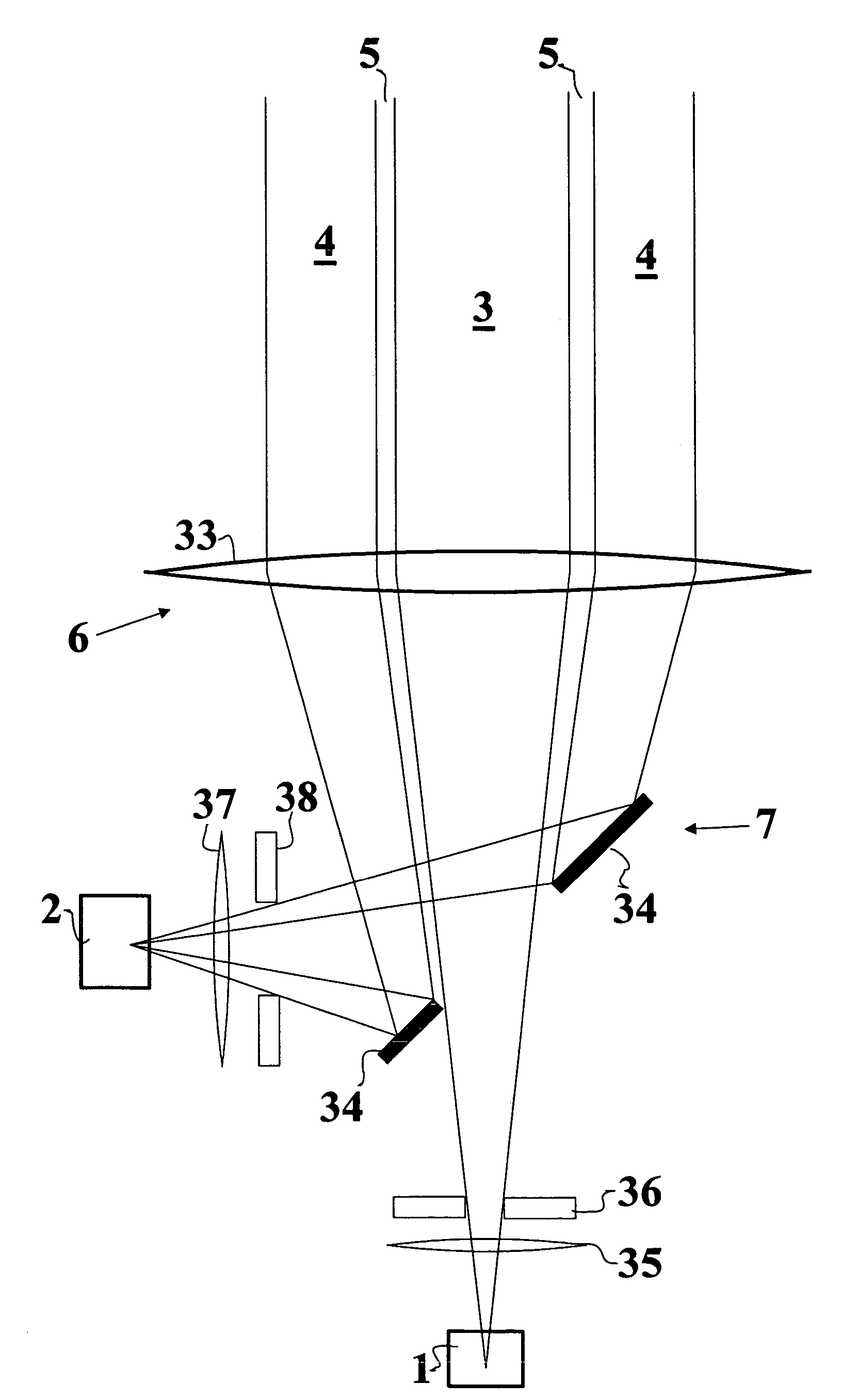
[0048]The solution of FIG. 3 includes an integrated optical component 6 and a reflecting element 7, with the aid of which a transmitter beam 3 and a receiver beam 4 are formed. The integrated optical component 6 consists of, in this solution, a single lens 33. A mirror 34, in the centre of which a hole has been made, acts in turn as the reflecting element 7. The mirror 34 is positioned in such a way that the light obtained from the transmitter 1, which is located at the focal point of the lens 33, is directed through the hole in the mirror 34 to the central area of the lens 33, where it is refracted to form a transmitter beam of the desired shape. The mirror 34, however, is positioned so that the light arriving from the area of the desired receiver beam to the edge area of the lens 33 is refracted and reflected towards the reflected focal point. The receiver 2 is located at this reflected focal point.

[0049]In the basic solution of the embodiment of FIG. 3, there are thus four optica...


PUM


Abstract

A lidar, which includes a transmitter and a receiver, as well as an optical system, which is arranged to direct at least part of the light sent by the transmitter as a transmitter beam progressing towards an object and to define the receiver beam to the receiver, at least part of the light arriving from the zone of which is focussed on the receiver. The optical system of the lidar is implemented in such a way that the beams immediately in front of the lidar are located essentially outside of each and one of the beams at least partially surrounds the other beam. The optical system includes an integrated optical, which has a first area for forming the transmitter beam, and a second area for forming the receiver beam.

Description

CROSS-REFERENCE TO RELATED APPLICATION[0001]The present application claims priority under 35 U.S.C. §119 to PCT Patent Application No. PCT / FI03 / 00143, filed Feb. 28, 2003, and Finnish Patent Application No. 20020394, filed Feb. 28, 2002, the entire contents of which are hereby incorporated by reference.BACKGROUND OF THE INVENTION[0002]1. Field of the Invention[0003]The present invention relates to a lidar.[0004]2. Description of Background Art[0005]A lidar of this kind is used to perform measurements, in such a way that a transmitter beam is sent towards the object to be measured and the returning signal coming back from the direction of the object being measured is observed. The return signal is formed when the light of the transmitter beam is scattered and / or reflected by the object being measured.[0006]The lidars to which the present invention relates are particularly used for making meteorological measurements. The commonest measurements performed with the aid of the lidar are c...

Claims


Application Information

Patent Timeline
IPC IPC(8): G01C3/08G01N21/00G01S7/481G01S17/95
CPCG01S17/95G01S7/4812Y02A90/10
Inventor KALLIO, JUKKA
Owner VAISALA
Why Eureka
Try Eureka