Magnetoresistive element, magnetic head, magnetic storage unit, and magnetic memory unit

a technology of magnetoresistance and magnetic head, applied in the field of magnetoresistance elements and magnetic heads, can solve the problems of reducing the output of the magnetoresistance element, reducing the substantial change in the magnetoresistance, and causing the performance to be affected, and achieve good sensitivity

Inactive Publication Date: 2008-09-23
FUJITSU LTD
View PDF5 Cites 9 Cited by
  • Summary
  • Abstract
  • Description
  • Claims
  • Application Information

AI Technical Summary

Benefits of technology

[0012]According to one embodiment of the present invention, there is provided a magnetoresistive element in which the above-described disadvantage is eliminated.
[0013]According to one embodiment of the present invention, there is provided a high-output magnetoresistive element having good sensitivity for detecting a magnetic field.

Problems solved by technology

In this case, in the CIP structure, the current density of sense current increases so that the degradation of performance may be caused because of the migration of a material forming the spin-valve film due to overheating.
This reduces a substantial change in magnetoresistance, thus decreasing the output of the magnetoresistive element.
Further, if the coercive force is too high, the magnetization of the free magnetization layer hardly rotates because of the signal magnetic field, so that little output may be obtained.

Method used


Image

  • Magnetoresistive element, magnetic head, magnetic storage unit, and magnetic memory unit
  • Magnetoresistive element, magnetic head, magnetic storage unit, and magnetic memory unit
  • Magnetoresistive element, magnetic head, magnetic storage unit, and magnetic memory unit

Examples


first embodiment

[0053]A description is given of a composite magnetic head including a magnetoresistive element and an induction-type recording element according to a first embodiment of the present invention.

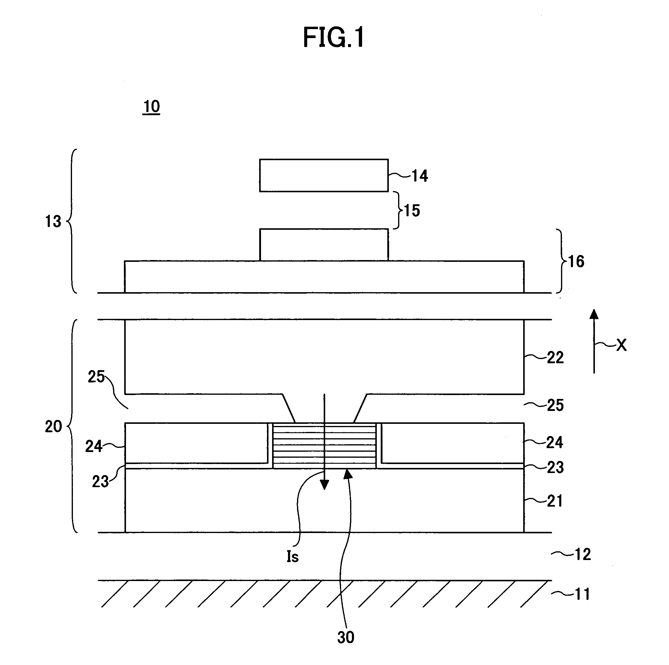
[0054]FIG. 1 is a diagram showing part of the medium opposing surface of a composite magnetic head 10 according to the first embodiment. In FIG. 1, the direction of the arrow X indicates the direction of movement of a magnetic recording medium (not graphically illustrated) opposing a magnetoresistive element 20.

[0055]Referring to FIG. 1, the magnetic head 10 includes the magnetoresistive element 20 formed on a flat ceramic substrate 11 of Al2O3—TiC or the like serving as the base body of a head slider, and an induction-type recording element 13 formed thereon.

[0056]The induction-type recording element 13 includes an upper magnetic pole 14, a lower magnetic pole 16, a yoke (not graphically illustrated) connecting the upper magnetic pole 14 and the lower magnetic pole 16 magnetically, and a coil ...

example implementation

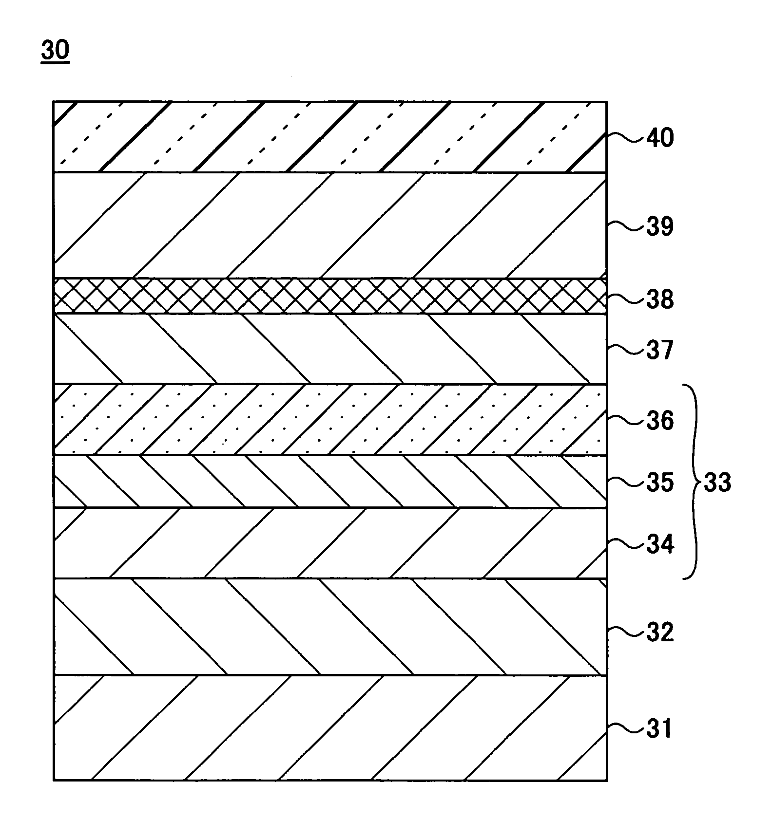
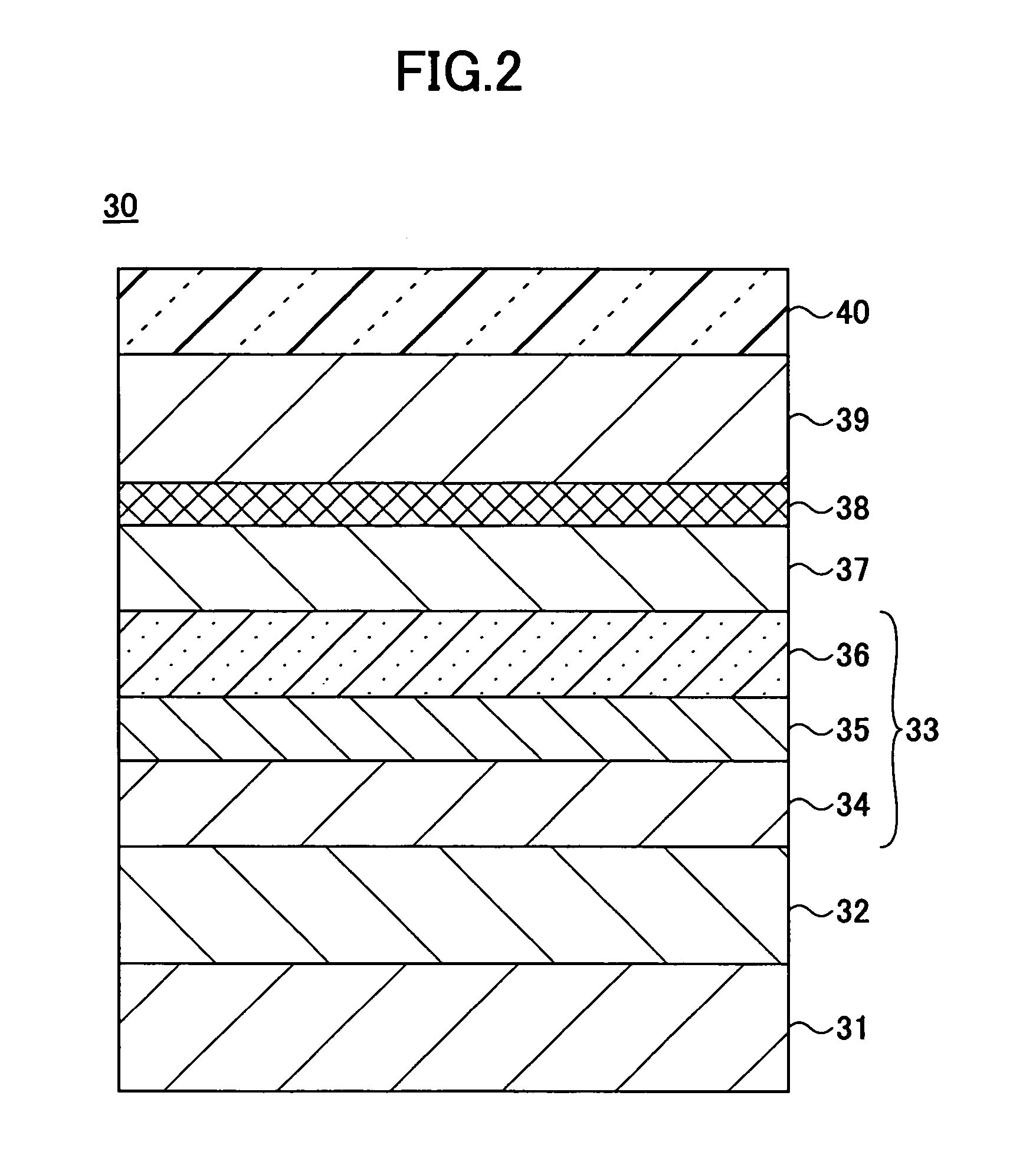
[0119]In an example implementation, magnetoresistive elements having the configuration of the GMR film 80 of the fifth example of the first embodiment shown in FIG. 6 were made. The specific configuration of the GMR films of Samples No. 1 through No. 20 of the example implementation is shown below. The parenthesized numeric values show film thickness, which remains the same through the example implementation.

[0120]Underlayer: NiCr (4 nm)

[0121]Lower antiferromagnetic layer: IrMn (5 nm)

[0122]Lower first fixed magnetization layer: Co60Fe40 (3.5 nm)

[0123]Lower non-magnetic coupling layer: Ru (0.7 nm)

[0124]Lower interface magnetic layer: CoFe (0.5 nm)

[0125]Lower second fixed magnetization layer: Co100-X-YMnXAlY

[0126]Lower second diffusion prevention layer: CoFe (0.5 nm)

[0127]Lower non-magnetic metal layer: Cu (3.5 nm)

[0128]Lower first diffusion prevention layer: CoFe (0.5 nm)

[0129]Free magnetization layer: Co100-X-YMnXAlY

[0130]Upper first diffusion prevention layer: CoFe (0.5 nm)

[0131]...

second embodiment

[0157]A magnetic head according to a second embodiment of the present invention includes a magnetoresistive element having a tunneling magnetoresistive (TMR) film. The magnetic head according to the second embodiment may have a configuration substantially the same as that of the magnetic head 10 shown in FIG. 1 except that a TMR film replaces the GMR film 30 forming the magnetoresistive element 20 of the magnetic head 10. Accordingly, a description of the magnetic head according to the second embodiment is omitted. A description is given below of five examples (first through fifth examples) with respect to the TMR film forming the magnetoresistive element 20. Any of the TMR films of the first through fifth examples may be applied to the magnetoresistive element 20.

[0158]FIG. 11 is a cross-sectional view of a TMR film 90 of the first example forming the magnetoresistive element 20 according to the second embodiment. In FIG. 11, the same elements as those described above are referred ...


PUM

PropertyMeasurementUnit
thicknessaaaaaaaaaa
thicknessaaaaaaaaaa
thicknessaaaaaaaaaa

Abstract

A CPP-type magnetoresistive element including a fixed magnetization layer, a non-magnetic metal layer, and a free magnetization layer that are stacked, and a diffusion prevention layer is disclosed. The free magnetization layer includes CoMnAl. The diffusion prevention layer is provided between the non-magnetic metal layer and the free magnetization layer so as to prevent Mn included in the free magnetization layer from diffusing into the non-magnetic metal layer. CoMnAl has a composition within the area formed by connecting Point A (44, 23, 33), Point B (48, 25, 27), Point C (60, 20, 20), Point D (65, 15, 20), Point E (65, 10, 25), Point F (60, 10, 30), and Point A with straight lines in this order in a ternary composition diagram where coordinates of the composition are expressed as (Co content, Mn content, Al content) with each of the Co, Mn, and Al contents being expressed in atomic percentage.

Description

CROSS-REFERENCE TO RELATED APPLICATION[0001]The present application is based on Japanese Priority Patent Applications No. 2005-346065, filed on Nov. 30, 2005, and No. 2006-062944, filed on Mar. 8, 2006, the entire contents of which are hereby incorporated by reference.BACKGROUND OF THE INVENTION[0002]1. Field of the Invention[0003]The present invention relates generally to magnetoresistive elements and magnetic heads for reproducing information in a magnetic storage unit, magnetic storage units, and magnetic memory units, and more particularly to a magnetoresistive element having a CPP (Current-Perpendicular-to-Plane) structure where sense current is caused to flow in the stacking direction of the stacked films forming the magnetoresistive element.[0004]2. Description of the Related Art[0005]In recent years, in the magnetic head of a magnetic storage unit, a magnetoresistive element has been employed as a reproduction element for reproducing information recorded in a magnetic record...

Claims


Application Information

Patent Timeline
Patent Type & Authority Patents(United States)
IPC IPC(8): G11B5/39
CPCB82Y25/00G01R33/093G11B5/3906G11C11/16H01L43/08H01F10/3281H01F10/3254H01F10/3263H01F10/3272H10N50/10G11B5/39
Inventor JOGO, ARATAOSHIMA, HIROTAKAIBUSUKI, TAKAHIROSHIMIZU, YUTAKAUZUMAKI, TAKUYA
Owner FUJITSU LTD
Why Eureka
Try Eureka